Inter-labial pad

a technology of inter-labial pads and pads, which is applied in the field of inter-labial pads, can solve the problems of difficulty in implementing conventional inter-labial pads, and achieve the effects of preventing foreign body sensation, increasing the compression repulsive force of inter-labial pads, and ensuring safety

Inactive Publication Date: 2005-12-08
UNI CHARM CORP
View PDF8 Cites 1 Cited by
  • Summary
  • Abstract
  • Description
  • Claims
  • Application Information

AI Technical Summary

Benefits of technology

[0042] According to this embodiment of the invention, the width of the backward end is within a range from 0.5 to 5 mm, and the width for the forward end is from 3 to 15 mm. In a case when the width for the top portion is within the range described above, it is possible to prevent foreign-body sensation given to a wearer and increase the compression repulsive force of the inter-labial pad. The width for the backward end is particularly preferably within a range from 1 to 3 mm, and the width for the forward end is particularly preferably from 4 to 10 mm. Further, while the width for the forward end and the width for the backward end may be changed discontinuously, it is preferred to constitute the top portion such that the width is continuously changed gradually since gaps are hardly generated between the pad and the labial inner wall.
[0043] According to this embodiment of the present invention, the inter-labial pad can be inserted easily and reliably while preventing deformation of the inter-labial pad or injuries given to the inside of the labia.

Problems solved by technology

As has been described above, it was difficult for the conventional inter-labial pad to prevent injury for the inside of the labia and easily find a point of inserting.

Method used


Image

  • Inter-labial pad
  • Inter-labial pad
  • Inter-labial pad

Examples


first embodiment

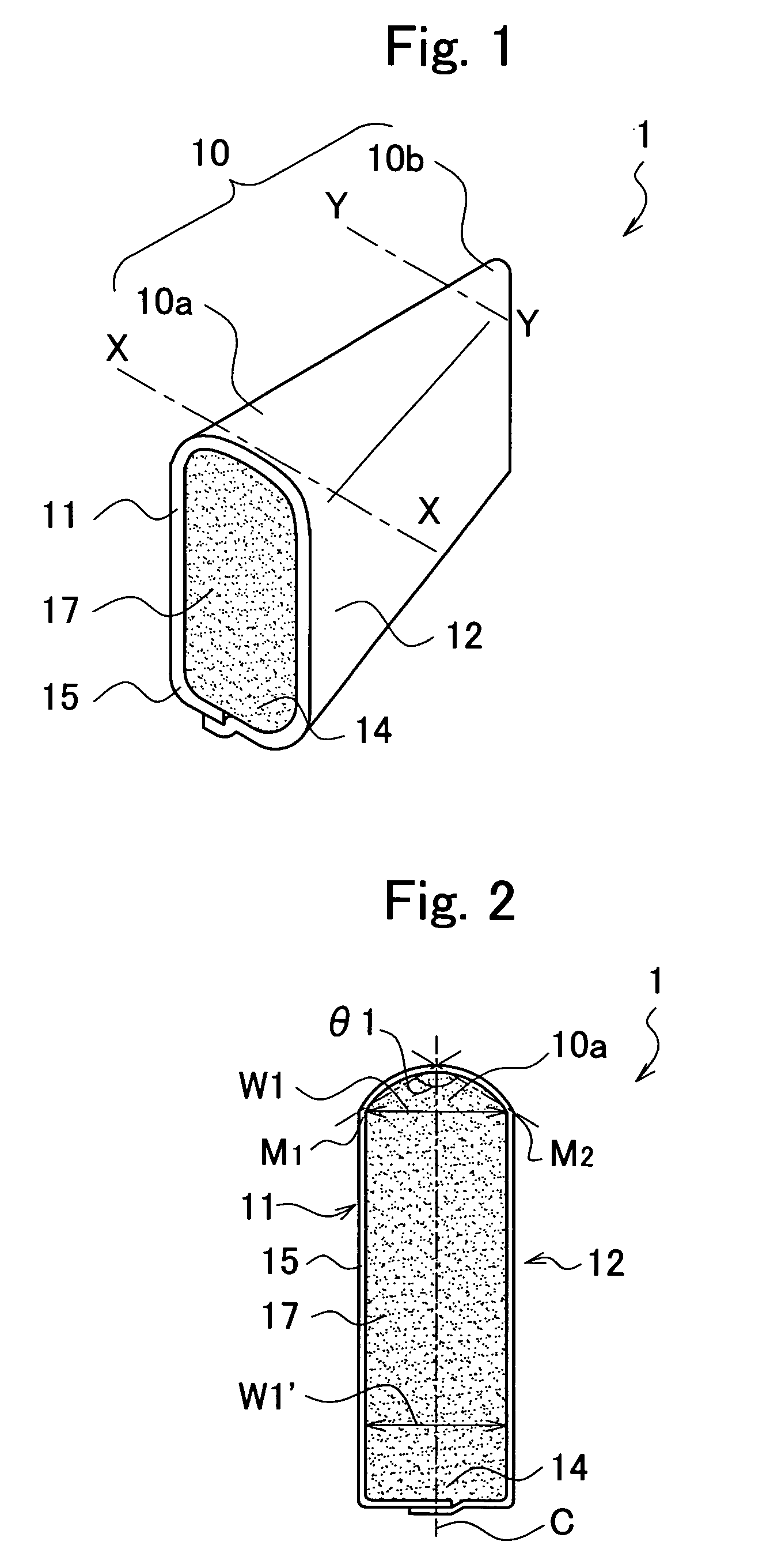
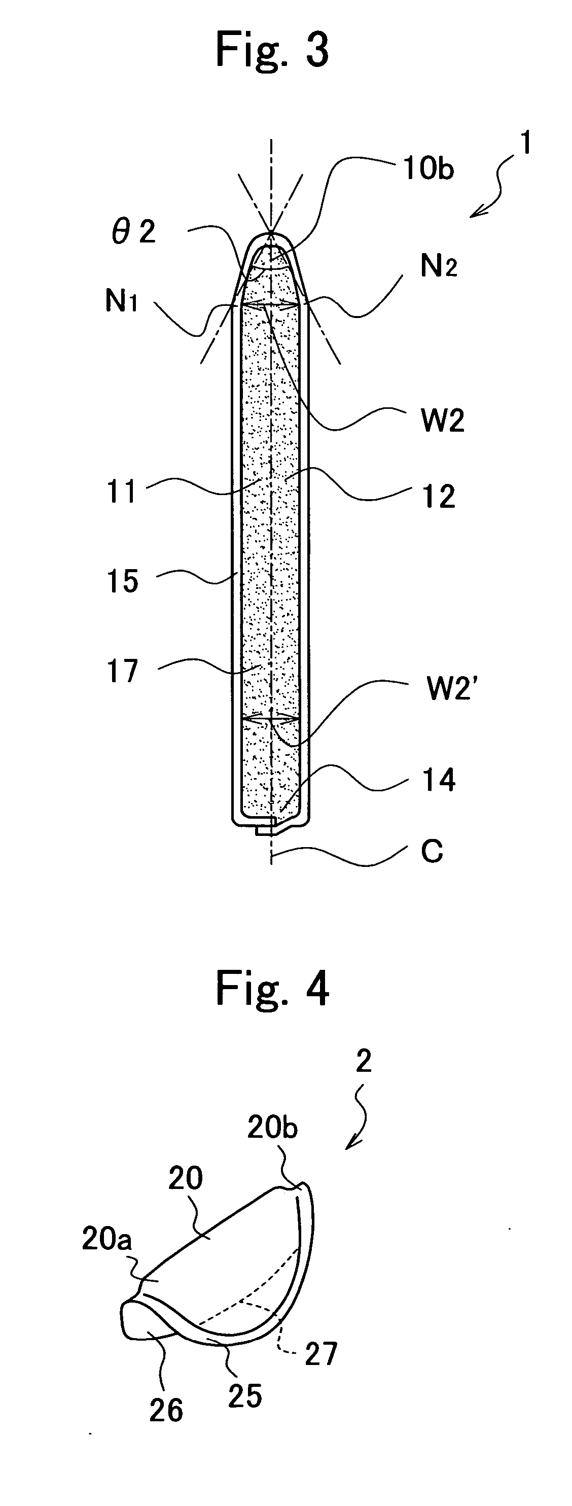
[0067]FIG. 1 is an entire perspective view of an inter-labial pad 1 according to a first embodiment of the present invention. In the inter-labial pad 1, when the inter-labial pad is attached to wearer's labia, a portion in contact with a forward portion of labia is referred to as a forward portion, while a portion in contact with the backward portion of labia is referred to as a backward portion. FIG. 1 shows a situation where the inter-labial pad 1 is viewed from the forward side. FIG. 2 is a cross sectional view along line X-X and FIG. 3 is a cross sectional view along line Y-Y of the inter-labial pad 1.

[0068] The inter-labial pad 1 is substantially in a pillow-like shape comprising an absorbent body 17, and a surface side sheet 15 as a cover sheet in which a substantially semi-cylindrical top portion 10 extends in the longitudinal direction. Lateral side portions 11 and 12 are provided on both sides of the top portion 10. The inter-labial pad 1 is inserted between the labia such...

second embodiment

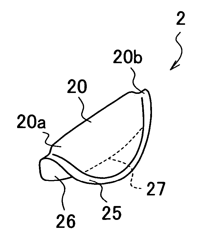
[0075] Then, an inter-labial pad 2 according to a second embodiment of the present invention will be described with reference to FIGS. 4 to 11. An inter-labial pad 2 comprises an absorbent body 27 substantially of a plate-like shape in the plan view, a surface side sheet 25 and a back face sheet 26 covering the absorbent body 27. In this embodiment, the cover sheet comprises a liquid permeable surface side sheet 25 and a less liquid permeable back face sheet 26.

[0076]FIG. 4 is an entire perspective view for the inter-labial pad 2 as viewed from the forward side in which the inter-labial pad 2 is folded in two along the longitudinal center line such that the opposed side portions of the back face sheet 26 come in contact with each other and a top portion 20 extending from the forward to the backward of the inter-labial pad 2 is formed along the fold. Both sides of the top portion 20 are lateral side portions 21, 22 in contact with the labial inner walls in the inserted state of the ...

third embodiment

[0081] Further, an inter-labial pad 3 of a third embodiment which is a modified embodiment of the inter-labial pad 2 of the second embodiment will be explained. FIG. 12 is a plan view in a state of putting a finger F to the side of a back face sheet 36 of an inter-labial pad 3, as viewed on the side of a top portion 30. The inter-labial pad 3 has an identical constitution with that of the inter-labial pad 2 excepting that adhesives are coated to side portions of the back face sheet 36 on the forward and side portions of the back face sheet 36 on the forward are adhered to each other.

[0082] Since the side portions of the back face sheet 36 on the forward are adhered to each other, the width W32 and the angle for the forward end 30a of the top portion 30 scarcely change even when the finger is put on the inter-labial pad 3. Thus, even in a case where the forward of the labia is not easy to open, the inter-labial pad 3 can intrude easily also to the forward of the labia, and the forwa...


PUM


Abstract

An inter-labial pad which can be inserted easily to a point of insertion is provided. An inter-labial pad 1 having an absorbent body for absorbing a body fluid is covered with a cover sheet, wherein a top portion 10 to be in contact with the depth of labia when the inter-labial pad 1 is put between the labia is provided. The top portion 10 has a shape different between the forward end 10a coming in contact with the forward of the labia and the backward end 10b coming in contact with the backward of the labia upon attachment, with the backward end being in a sharp shape and of narrow width and sharp angle. Thus, the inter-labial pad 1 can be inserted easily from a sharp backward end 10b easily to the labia.

Description

CROSS-REFERENCE TO RELATED APPLICATIONS [0001] This application is based upon and claims the benefit of priority from Japanese Patent application No. 2004-160162 filed on May 28, 2004, the entire contents of which is incorporated herein by reference. FIELD OF THE INVENTION [0002] The present invention relates to a sanitary article in which an absorbent body that absorbs a body fluid is covered with a cover sheet and, specifically, an inter-labial pad which is used being inserted between labia and, more in particular, it relates to the an inter-labial pad easily attached to the labia. RELATED ART [0003] Sanitary napkins and tampons have been used generally as female sanitary articles. For the sanitary napkins, a great effort has been made in order to prevent leakage of menstrual blood from a gap caused by insufficient adhesion to the vicinity of ostium vaginae. Further, also for the tampons, since they cause foreign-body sensation, uncomfortable feeling upon wearing and difficulty in...

Claims


Application Information

Patent Timeline
Patent Type & Authority Applications(United States)
IPC IPC(8): A61F13/15A61F13/472A61F13/514
CPCA61F13/47209A61F13/15A61F13/45A61F13/472A61F13/514
Inventor MIZUTANI, SATOSHIYOSHIMASA, WATARUNODA, YUKI
Owner UNI CHARM CORP
Why Eureka
Try Eureka