Dispensing tip

a technology of tip and drop, which is applied in the direction of eye treatment, movable measuring chamber, instruments, etc., can solve the problem of dispensing small droplets of fluid, and achieve the effect of enhancing sharp demarcation and minimizing surface area

Active Publication Date: 2005-12-15
ALLERGAN INC
View PDF10 Cites 57 Cited by
  • Summary
  • Abstract
  • Description
  • Claims
  • Application Information

AI Technical Summary

Benefits of technology

[0002] Heretofore, many types of dispenser tips have been utilized for the purpose of transferring accurately measured small droplets of liquid.
[0008] A surface revolution surrounding the egress orifice is provided for enabling droplet separation from the egress orifice. In this manner, uniform droplet formation is effected which can be independent of dispenser tip orientation during droplet dispensing.
[0011] Preferably, the concave arcuate surface abuts the egress orifice in order to minimize surface area onto which a formed droplet can adhere.
[0012] To further enhance a sharp demarcation between the arcuate surface and the egress orifice, the arcuate surface may depend from the egress orifice and angle of about 60°.

Problems solved by technology

One of the primary problems encountered with dispensing small droplets of fluid occurs as a result of the physical phenomenon of interfacial tension and surface energy.

Method used


Image

  • Dispensing tip
  • Dispensing tip
  • Dispensing tip

Examples


Embodiment Construction

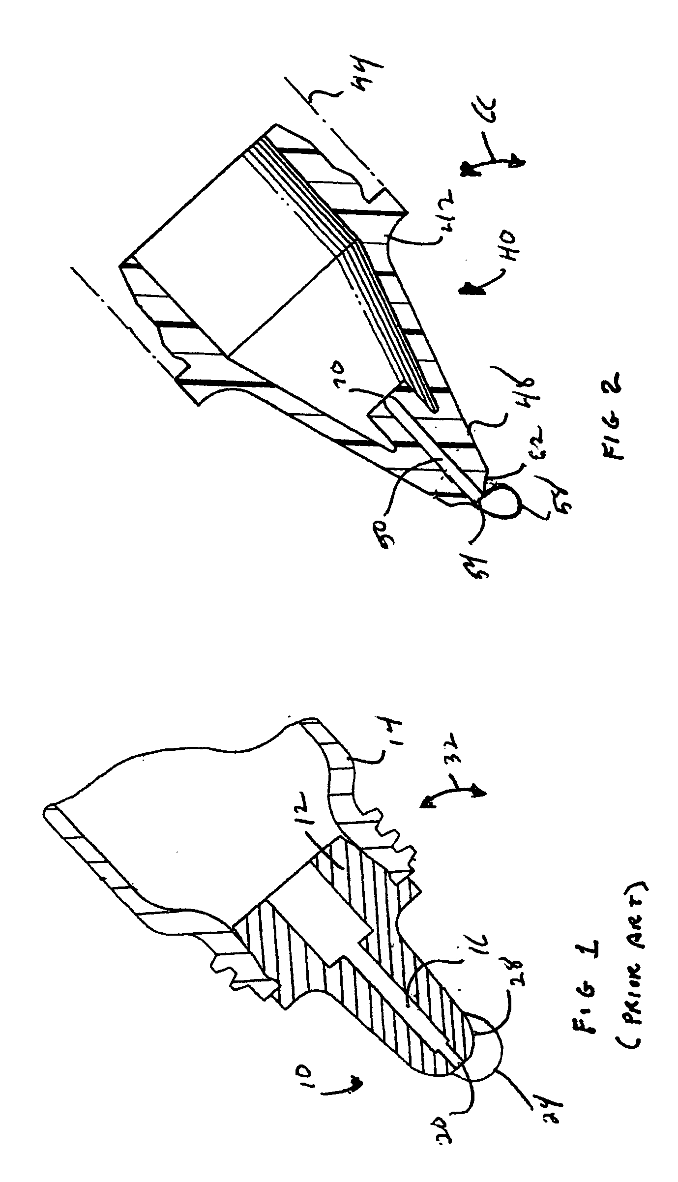
[0019] With reference to FIG. 1, there is shown a prior art dispensing tip 10 including a body 12 suitable for attachment to a bottle 14 and having a lumen 16 in fluid communication with an egress orifice 20.

[0020] As illustrated, droplet formation caused by squeezing of the bottle 14 thus forcing a fluid through the lumen 16 and orifice 20 creates a droplet 24 which by either capillary or surface tension adheres to a surface 28 surrounding the egress orifice thus enabling the droplet 24 to grow in size depending upon the angular orientation of the dispensing tip 10 as indicated by the arrow 32.

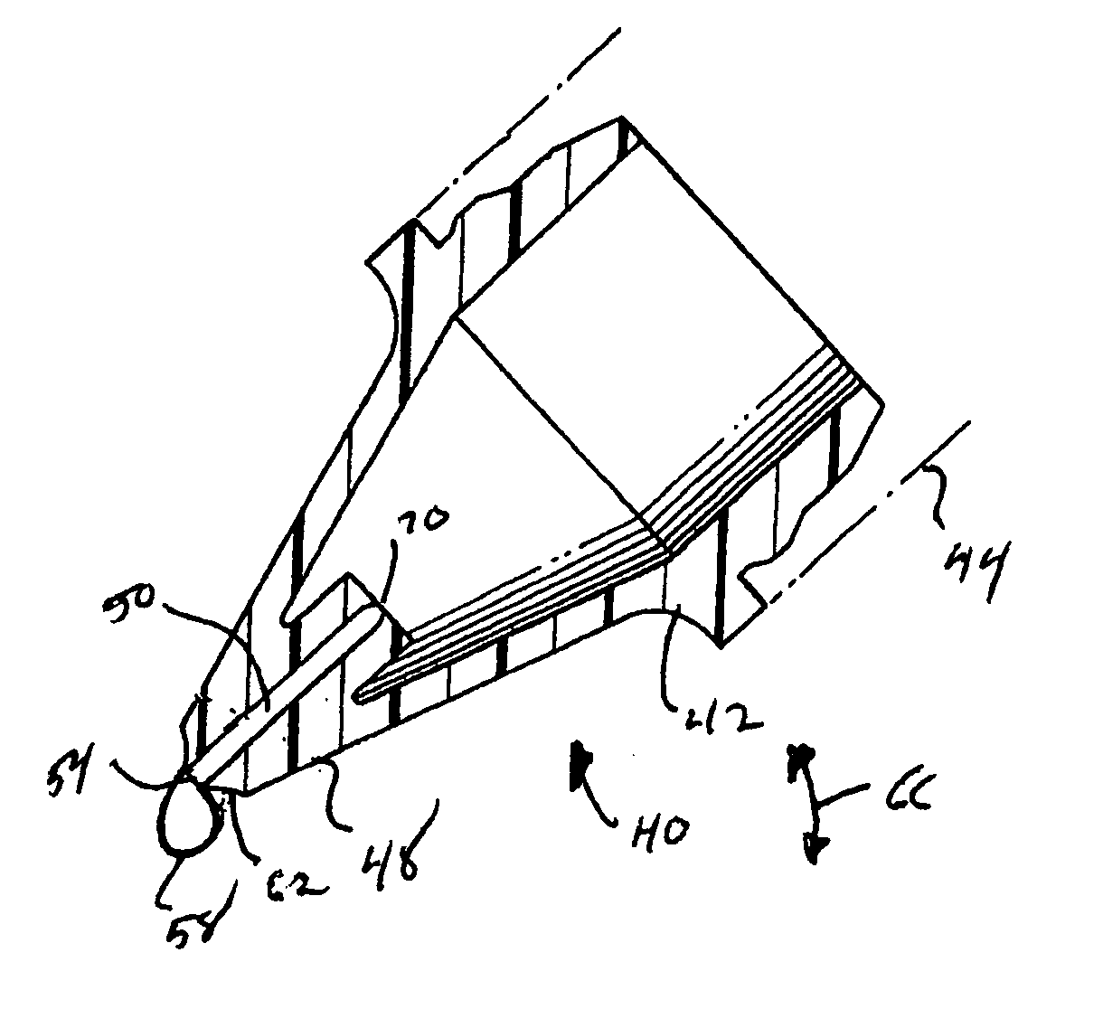
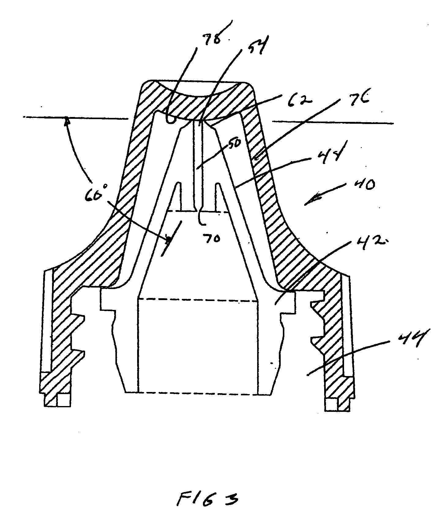
[0021] With reference to FIG. 2, there is shown a dispensing tip 40 in accordance with the present invention which also includes a body 42 suitable for attachment to a bottle 44 which includes a nozzle 48 having a lumen therethrough for the flow of a liquid formulation and an egress orifice 54 in fluid communication with the lumen 50 for the formation of a droplet 58. A concave arcuate surf...


PUM


Abstract

A dispensing tip includes a body suitable for attachment to a dispensing bottle along with a nozzle having a lumen therethrough for flow of liquid formulation and an egress orifice which is in fluid communication with the lumen for the formation of droplets. A concave arcuate surface of revolution about the egress orifice is provided and depending therefrom for enhancing droplet separation from the egress orifice which in turn insures uniform droplet formation and dispensement.

Description

[0001] The present invention is generally related to a control drop dispensing system and is more particularly directed to a dispensing tip for enabling the formation of small uniform droplets of a liquid formulation. [0002] Heretofore, many types of dispenser tips have been utilized for the purpose of transferring accurately measured small droplets of liquid. [0003] One of the primary problems encountered with dispensing small droplets of fluid occurs as a result of the physical phenomenon of interfacial tension and surface energy. Alone or in combination, these two phenomenon (if they can be differentiated) cause a droplet being forced out of the dispenser tip to enlarge in size until it is of a weight to overcome the work of adhesion between the liquid and the dispenser surface. [0004] Droplet size is dependent upon many factors and is often larger than the amount of liquid formulation desired to be dispensed. [0005] A number of dispensing tips have been designed to provide small...

Claims


Application Information

Patent Timeline
Patent Type & Authority Applications(United States)
IPC IPC(8): A61F9/00B05C5/02B65D47/18
CPCA61F9/0026B65D47/18
Inventor SPADA, LON T.BUTORAC, PAUL T.
Owner ALLERGAN INC
Why Eureka
Try Eureka