
Method for balancing color wheel and structure therof

a color wheel and structure technology, applied in the field of assembly methods of color wheel and the structure, can solve the problems of direct damage to the goodwill of the manufacturer, difficult to precisely remove the weight to reach a perfect rotational balance on the ring, and unbalance of the rotational balance of the color wheel

Inactive Publication Date: 2005-12-15
HON HAI PRECISION IND CO LTD
View PDF4 Cites 12 Cited by
  • Summary
  • Abstract
  • Description
  • Claims
  • Application Information

AI Technical Summary

Benefits of technology

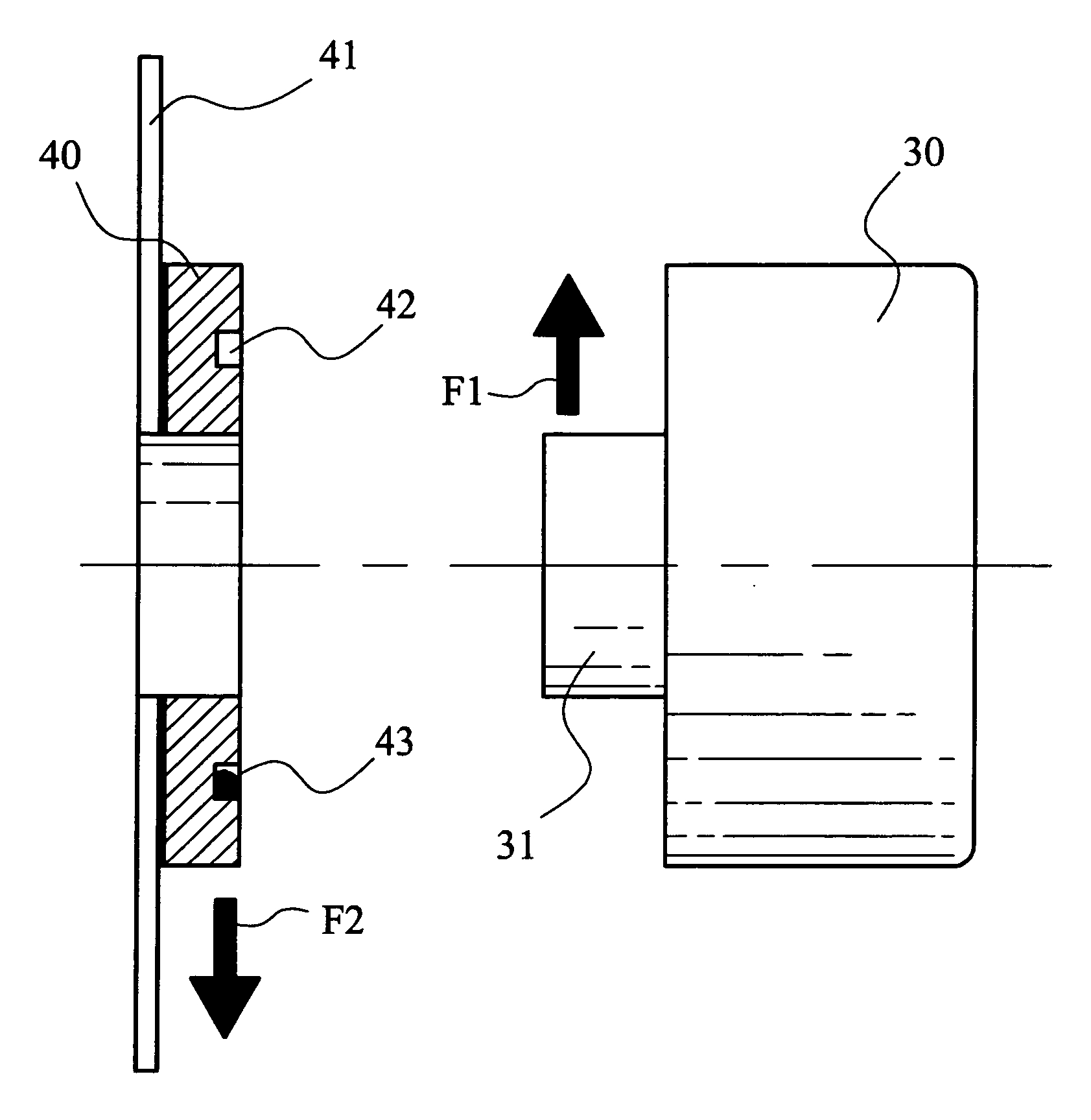
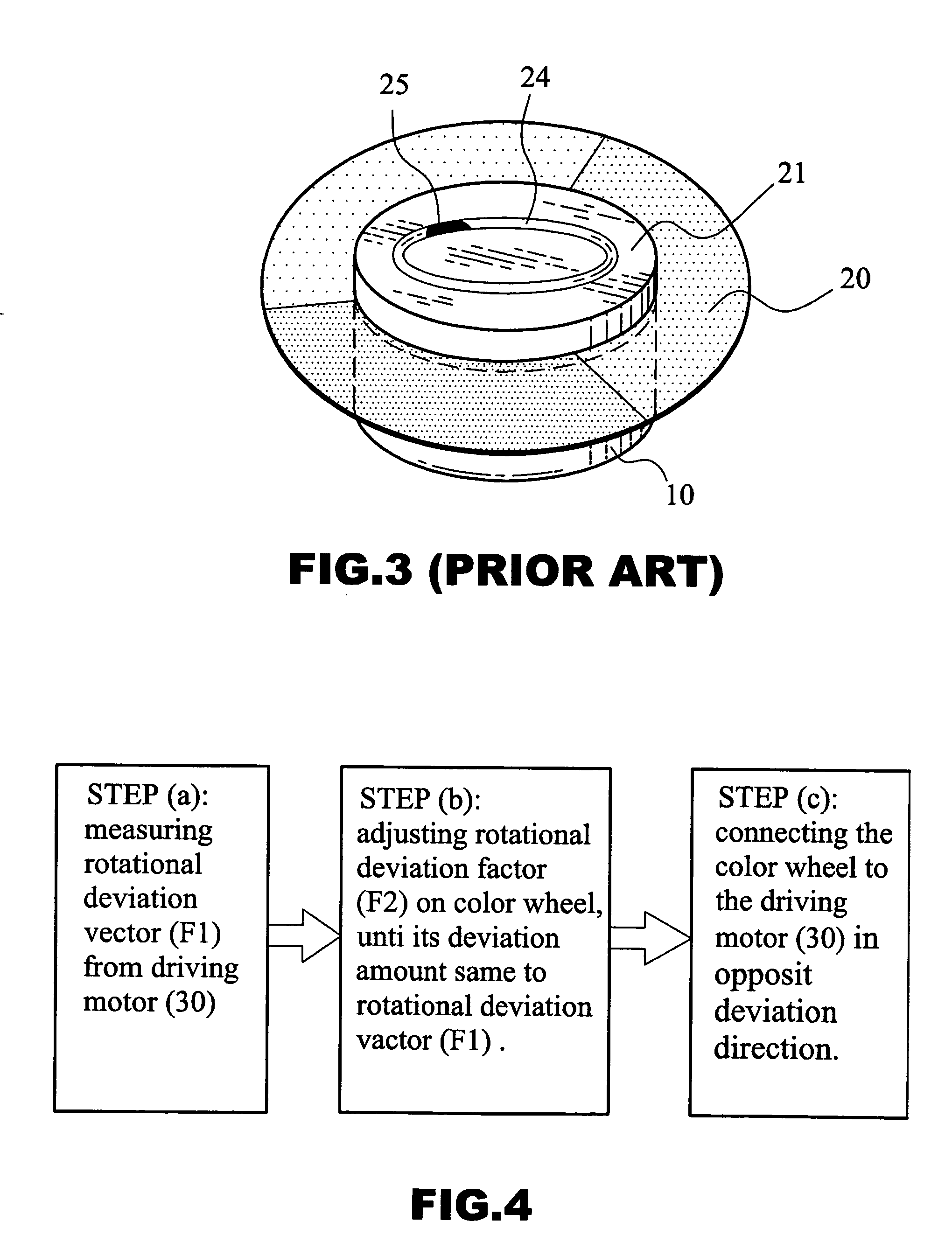
[0008] In accordance with the present invention, the method may comprising the steps of: (a), measuring the rotational deviation vector from a driving motor, including its deviation amount and direction; (b), adjusting the deviation of a color wheel to make its deviation amount be the same of the driving motor; and (c), connecting the color wheel to the driving motor and let the deviation direction thereof be opposite to each other to reach an expected balance. According to the present invention, an e...

Problems solved by technology

For instance, while the color wheel rotates in an extremely high speed, any rotational unbalance once occurred shall generate a high frequency noise, thus would damage the manufacturer's goodwill directly while in operation in meeting.
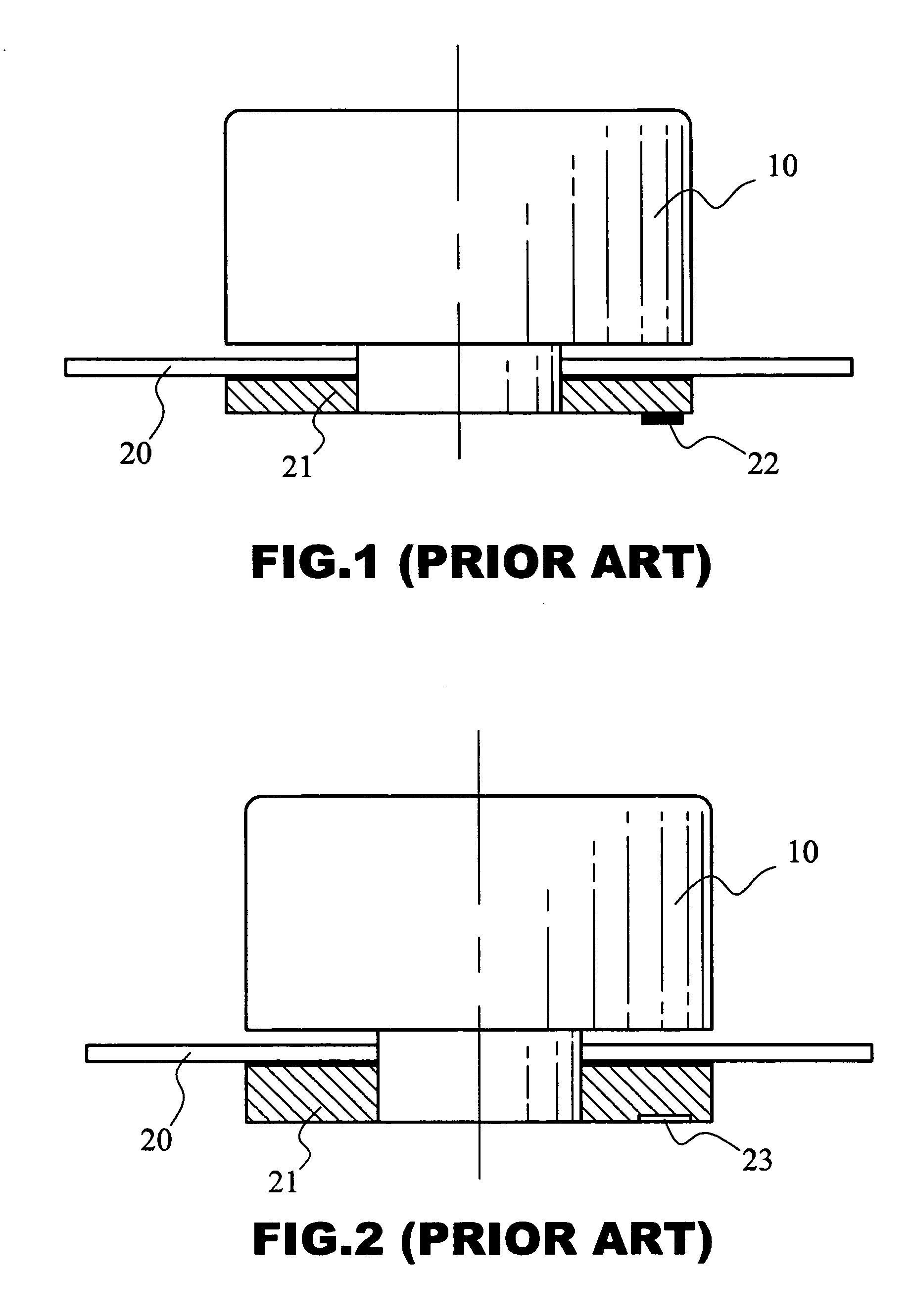
For the first method, due to the weight (22) has protruded from the surface which may arise unexpected noise by wind cut.
For the second method, we found that it is difficult to precisely remove the weight to reach a perfect rotational balance on the ring (21).
There are several factors could led to rotational unbalance of color wheel; for instance, most of the shaft (31) of the driving motor are naturally unbalanced in rotation, or the color filter which may also not be bonded on perfect position, or the thickness of adhesive layer may unevenly formed under the color filters.

Method used


Image

  • Method for balancing color wheel and structure therof
  • Method for balancing color wheel and structure therof
  • Method for balancing color wheel and structure therof

Examples


Embodiment Construction

[0015] As shown in FIG. 4 and FIG. 5, an embodiment of color wheel in accordance with the present invention, may comprise a ring (40) and a set of color filter (41). Preferably, to create an annular grove (42) on the ring (40) has. To compare with the annular groove (24) of FIG. 3 as the same disclosed in U.S. patent publication No. 2003 / 0035218 A1, the annular grove (24) on the ring (21) of the prior art is formed on the opposite side to the driving motor (10), and that would appeared on the outward appearance of the product. However, the annular grove (42) of the present embodiment would be hide when been assembled with a driving motor (30).

[0016] Referring again to FIG. 4. The method in accordance with the present invention, may including: step (a), measuring the rotational deviation vector (F1) from a driving motor (30), included the deviation amount and direction thereof, preferably; to apply a mark on the shaft (31) of the motor (30) to indicate the direction of rotational de...


PUM


Abstract

A method for balancing a color wheel comprising: step (a), measuring the rotational deviation vector of a driving motor, including its deviation amount and direction; step (b), adjusting the deviation of a color wheel to make its deviation amount to be the same of the driving motor; and step (c), connecting the color wheel to the driving motor and let the deviation direction thereof to be opposite to each other to reach an expected balance. According to the present invention, an embodiment of the color wheel structure may includes a set of color filter and a ring, before to start the assembly, adjusting the deviation vector of the ring and motor shaft first, and then to assemble it and make the deviation vectors oppositely.

Description

FIELD OF THE INVENTION [0001] The present invention relates to an assembly method for color wheel and the structure; and, more specifically, to a method comprising a step of measuring the rotational deviating vectors of a motor and a color wheel, and assembling them in opposite deviation direction. BACKGROUND OF THE INVENTION [0002] Digital Light Processing (DLP) has been well developed and applied in digital projector. Recently, the digital projector has shown a high potential to share traditional liquid crystal projector market; meanwhile, the key element, so-called color wheel for carrying a set of color filters has played an important role in determining the quality of the projector. For instance, while the color wheel rotates in an extremely high speed, any rotational unbalance once occurred shall generate a high frequency noise, thus would damage the manufacturer's goodwill directly while in operation in meeting. Therefore, how to improve the rotational balance of the color wh...

Claims


Application Information

Patent Timeline
IPC IPC(8): G01M1/30G02B7/00
CPCG01M1/30G02B26/008G02B7/006
Inventor CHUNG, CHIN-MINGHSU, PI-TSUNGLAI, CHIEN-CHIH
Owner HON HAI PRECISION IND CO LTD
Learn More