Geosteering in anisotropic formations using multicomponent induction measurements

a multi-component induction and geosteering technology, applied in seismology for water-logging, instruments, and using reradiation, etc., can solve the problems of not always being the case, and resistivity sensors being responsiv

Active Publication Date: 2005-12-15
BAKER HUGHES INC
View PDF31 Cites 23 Cited by
  • Summary
  • Abstract
  • Description
  • Claims
  • Application Information

AI Technical Summary

Problems solved by technology

A limitation of the method and apparatus used by Wu is that resistivity sensors are responsive to oil / water contacts for relatively small distances, typically no more than 5 m; at larger distances, conventional propagation tools are not responsive to the resistivity contrast between water and oil.
For MWD tools mounted on metal mandrels, those assumptions are not valid.
This may not always be the case in field applications where the borehole is approaching the bed boundary at an angle.
However, the method of Zhang, while extremely useful for wireline applications, may not be computationally fast enough to provide the angles in real time that are necessary for reservoir navigation.
Compared to Zhang, the method of Xiao has the added drawback of requiring HDIL measurements.

Method used


Image

  • Geosteering in anisotropic formations using multicomponent induction measurements
  • Geosteering in anisotropic formations using multicomponent induction measurements
  • Geosteering in anisotropic formations using multicomponent induction measurements

Examples


first embodiment

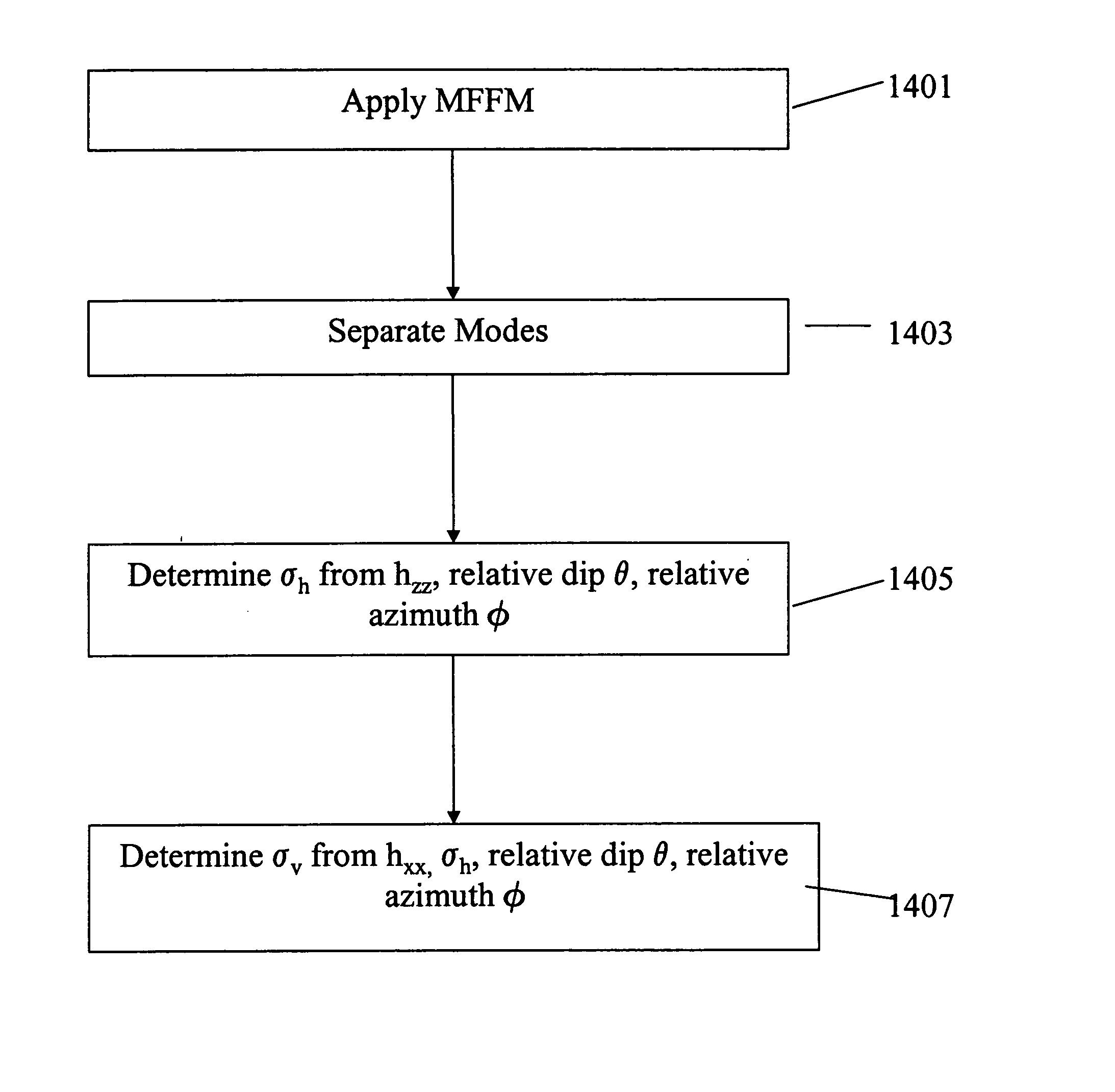
[0079]FIG. 12 shows a flowchart of an exemplary embodiment of the present invention. MFFM is applied using the 3DEX™ measurement tool (Box 1401). The obtained measurements are the components of the matrix of the left hand side of Eq. (23). If the angles θ and φ are known, separation of modes is then performed (Box 1403). Fundamental modes are typically the principal components xx and zz of the diagonalized multifrequency matrix. One way to separate the modes is by performing a least squares operation, for example, on Eq. (25). Acquisition of at least 2 or more independent components enable a solution of Eq. (25), having 2 unknown on its right-hand side. Thus, a requirement is that the number n1 of focused measurements must be at least, or must be capable of giving two independent measurements. In Box 1405, knowledge of zz, relative dip θ, and relative azimuth φ enables determination of the horizontal conductivity, σh using the standard prior art inversion methods, such as that descr...

second embodiment

[0080]FIG. 13 details an exemplary method of the invention for recovering formation dip and formation azimuth given the obtained MFFM components. Formation angles are determined simultaneously with the principal components. This is different from the method disclosed in Tabarovsky '045 where an iterative process is used for determination of formation angles. In Box 1501, the entire processing interval is subdivided into relatively small windows in which values of the relative formation dip and relative formation azimuth within the windows are substantially constant. The term “relative” refers to the formation dip and azimuth in a wellbore based coordinate system. We denote these angles by Θ and Φ. As shown in Box 1503, a number of incremental values of relative formation dip are selected from a range, such as from zero to ninety degrees at every logging depth. At every given logging depth and formation dip, the relative formation azimuth is changed incrementally from 0 to 360 degree...


PUM


Abstract

A multicomponent induction logging tool is used on a MWD bottomhole assembly. Multifrequency focusing that accounts for the finite, nonzero, conductivity of the mandrel is applied. Using separation of modes, the principal components and relative dip angles in an anisotropic medium are determined. The results are used for reservoir navigation in anisotropic media.

Description

CROSS REFERENCES TO RELATED APPLICATIONS [0001] This application is a continuation-in-part of U.S. patent application Ser. No. 10 / 934,596 filed on Sep. 3, 2004 and a continuation-in-part of U.S. patent application Ser. No. 10 / 867,619 filed on Jun. 15, 2004. This application is also related to a US patent application filed concurrently with the present application under attorney docket no. 414-40336-USD1BACKGROUND OF THE INVENTION [0002] 1. Field of the Invention [0003] The invention is related to the field of electromagnetic induction well logging for determining the resistivity of earth formations penetrated by wellbores. More specifically, the invention addresses the problem of using multicomponent induction measurements in an anisotropic formation for reservoir navigation using determined distances to an interface in the earth formation. [0004] 2. Description of the Related Art [0005] To obtain hydrocarbons such as oil and gas, well boreholes are drilled by rotating a drill bit a...

Claims


Application Information

Patent Timeline
Patent Type & Authority Applications(United States)
IPC IPC(8): G01V3/18G01V3/28
CPCG01V3/28
Inventor TABAROVSKY, LEONTYRABINOVICH, MICHAEL B.
Owner BAKER HUGHES INC
Why Eureka
Try Eureka