Support member for a bed frame

a support member and bed frame technology, applied in the field of support members, can solve the problems of difficult adjustment of the the damage of the l-shaped angle iron support member that is not particularly large, and the difficulty of conventional legs that extend downwardly from the angle iron support member to achieve the proper height of the support member. achieve the effect of expanding the leg

Active Publication Date: 2005-12-22
FINGER LAKES INTPROP
View PDF7 Cites 9 Cited by
  • Summary
  • Abstract
  • Description
  • Claims
  • Application Information

AI Technical Summary

Benefits of technology

[0014] Since the actual length that the leg extends from the housing is an important dimension and must be carefully controlled to avoid a bowing upwardly or downwardly of the support member, there is, in an embodiment of the present invention, a mechanism that allows the leg to self adjust for the correct length, that is, there is a mechanism that has an unlocked position where the leg is free to move axially with respect to the housing and can, in that position fall by gravity, or be pulled downwardly, to the floor contacting length and the mechanism then allows the user to place the mechanism into a locked position where the leg is locked into a parti...

Problems solved by technology

One of the difficulties, however, with the use of an L-shaped angle iron as the cross or support member is that the cross sectional profile of the L-shaped angle iron renders the member susceptible to a bending weakness, that is, for example, when the bed is slid along the floor, the leg supporting the support member and being dragged across the underlying floor can cause the support member to twist and the twisting action can damage an L-shaped angle iron support member that is not particularly resistant to such twisting action.
Thus, the problem with the use of an L-shaped angle iron is not limited to the possible bending caused by the leg being twisted by encountering a snag in a carpet as the leg...

Method used


Image

  • Support member for a bed frame
  • Support member for a bed frame
  • Support member for a bed frame

Examples


Embodiment Construction

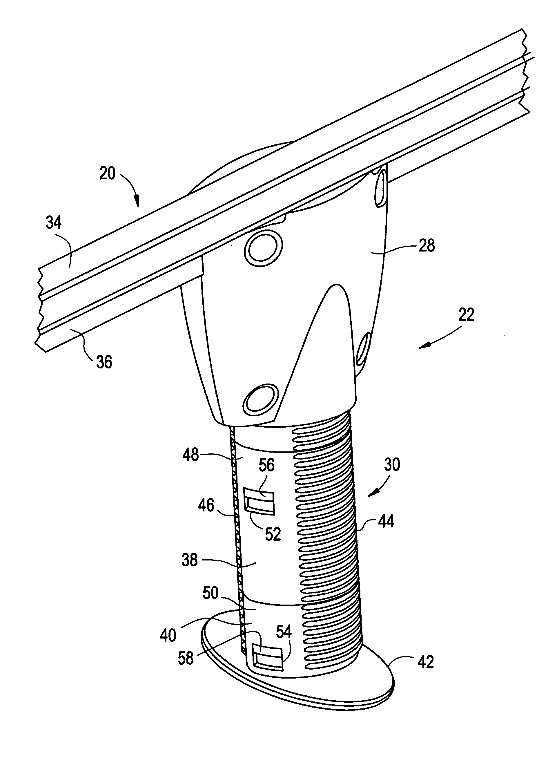
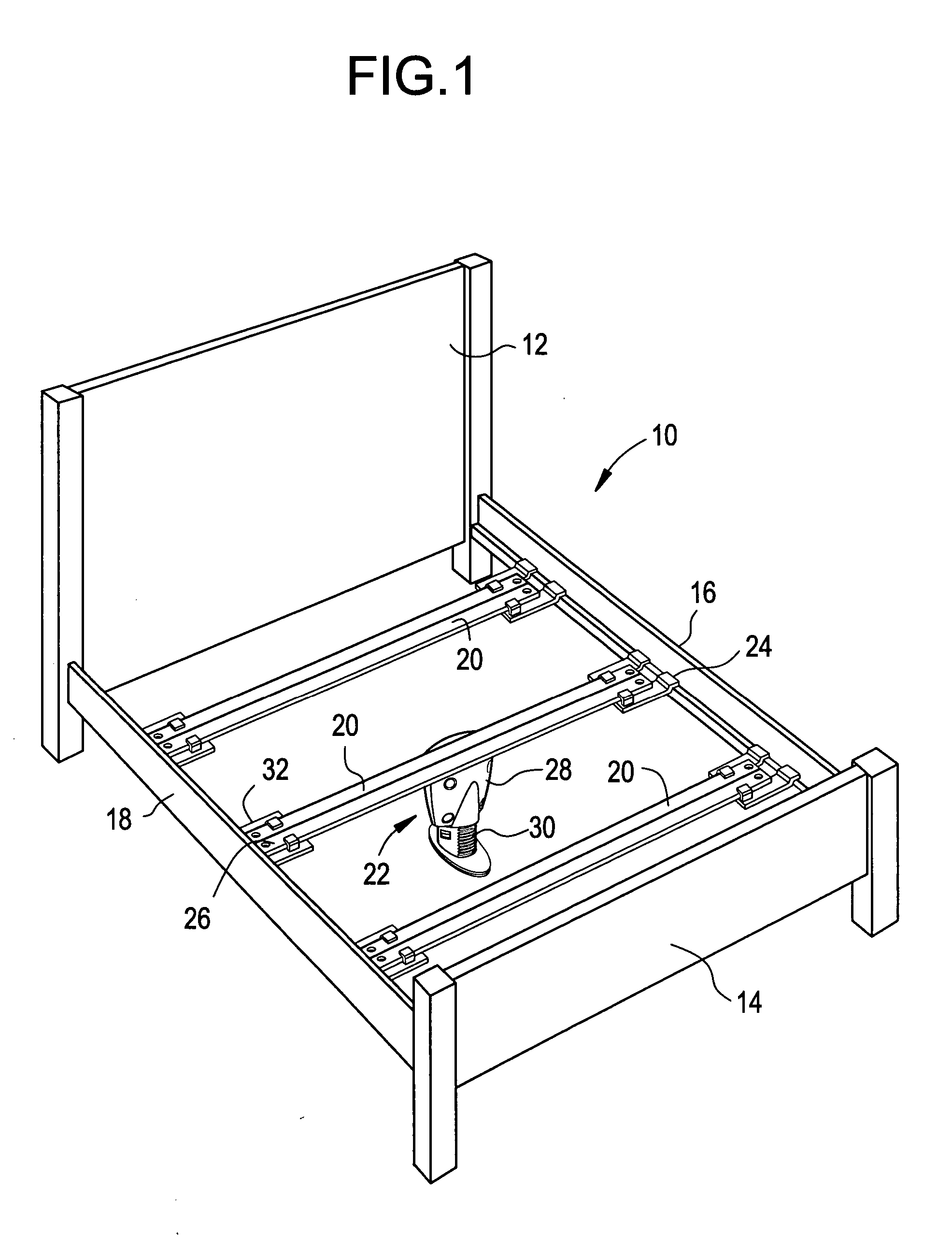
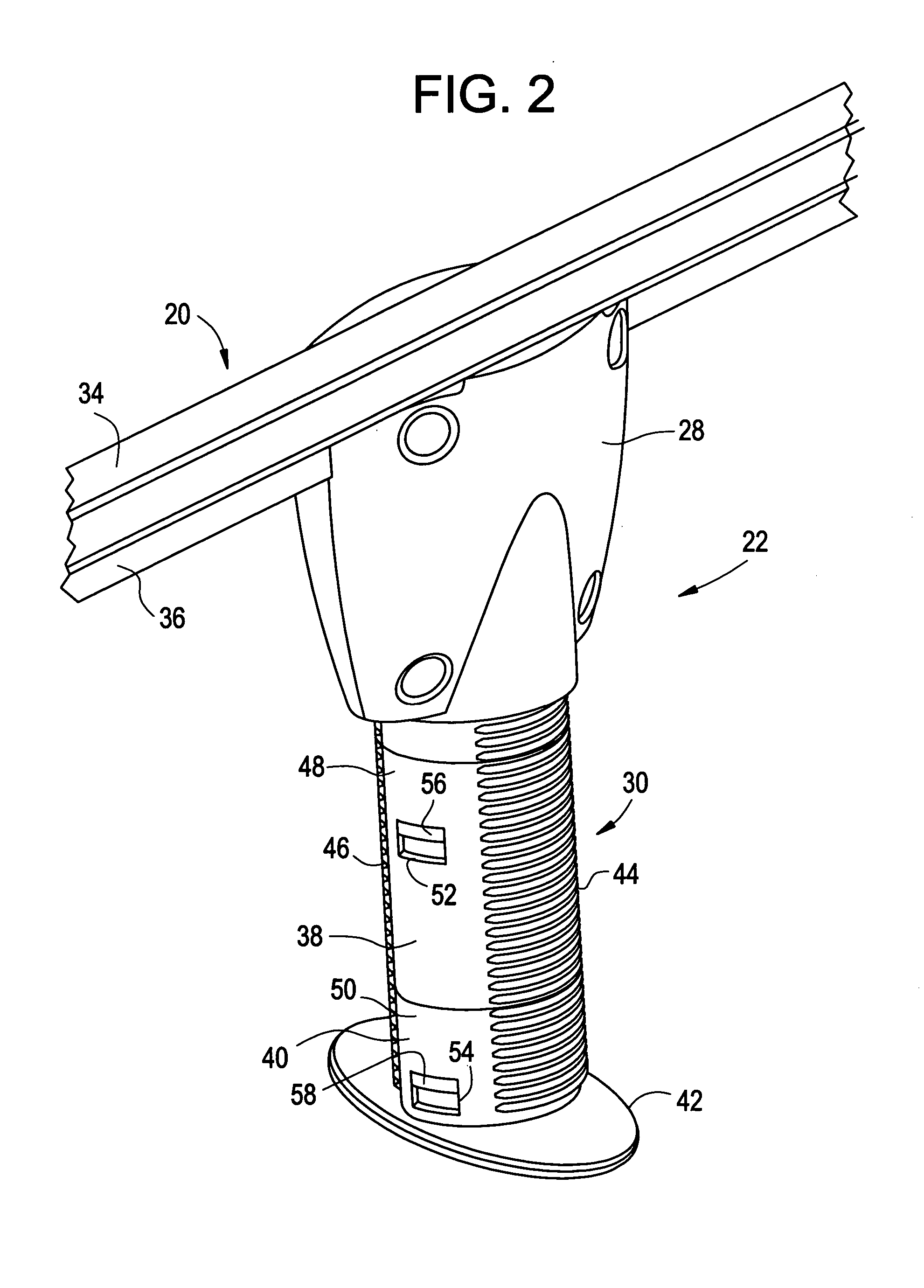
[0027] Referring now to FIG. 1, there is shown a perspective view of a bed frame 10 and which includes a head board 12, a footboard 14 and two parallel side rails 16, 18 both of which are shown to be wooden side rails. A bed frame 10 is used for illustrative purposes, it being seen that bed rails could also make use of the present invention. To make up the bed frame 10, there are also support members 20 that span between the parallel side rails 16, 18 and are affixed thereto. Leg assemblies 22, only one of which is shown, are affixed to the support member 20, generally about midway between the side rails 16, 18, or, alternatively, between the ends 24, 26 of the support member 20. The leg assembly 22 shown, is affixed to the support member 20 and extends downwardly therefrom to contact the underlying floor on which the bed frame 10 rests in order that the floor provide the necessary support for the support member 20. That support is, of course, necessary inasmuch as the support membe...


PUM


Abstract

A T-shaped support member that can be used with a bed frame or bed rails to provide support for a box spring and mattress. A leg assembly is affixed to the support member and is used to support the cross member. The leg assembly includes a housing having a leg that extends downwardly from the support member to contact the floor on which the bed frame or bed rails are located. The length the leg is extendable from the support member is self adjusting by a mechanism that can be twisted to an unlocked position to drop the leg downwardly quickly to contact the floor and then twisted back to lock the leg in that extended length.

Description

CROSS-REFERENCE TO RELATED APPLICATIONS [0001] The present application is based upon U.S. Provisional patent application 60 / 570,700, filed May 14, 2004 and entitled “SUPPORT MEMBER FOR A BEDFRAME”.BACKGROUND OF THE INVENTION [0002] The present invention relates to bed frames, and, more particularly, to a support member that spans and thus interconnects the side rails of a bed frame. [0003] In general, bed frames are comprised of a pair of generally parallel, spaced apart, side rails and one or more cross support members that span between the side rails in order to assemble and complete the bed frame structure. The bed frame, once assembled is adapted to support a box spring and a mattress to make up the bed itself. [0004] Conventionally, with a bed frame, the side rails can be metal angle irons or wooden side rails and the cross or support members can be wooden slats or can be other structural components such as angle irons that are L-shaped and which have legs that extends downward...

Claims


Application Information

Patent Timeline
IPC IPC(8): A47C19/00A47C19/02A47C19/04
CPCA47C19/024A47C19/027A47C19/025
Inventor POLEVOY, RICHARD S.CARLSON, PAUL ERICRYAN, HOWARD SCOTT
Owner FINGER LAKES INTPROP
Why Eureka
Try Eureka