
Collapsible wheelbarrow

a wheelbarrow and collapsible technology, applied in the field of wheelbarrows, can solve the problems of large storage space, limited storage space in sheds, garages, garages, etc., and achieve the effects of convenient assembly, simple lock, and strong legs

Inactive Publication Date: 2005-04-28
AMES TRUE TEMPER
View PDF24 Cites 5 Cited by
  • Summary
  • Abstract
  • Description
  • Claims
  • Application Information

AI Technical Summary

Benefits of technology

[0008] An improved support and resulting wheelbarrow in accordance with the present invention meets these needs and other needs. The improved wheelbarrow includes a pair of legs that are each configured as four-bar linkages and are collapsible. Each of the legs includes an advantageously simple lock for releasably locking the leg in extended and retracted positions. The wheelbarrow includes a frame assembly, a wheel, a tray, and a pair of handles. The frame assembly can be assembled by the manufacturer, and the wheelbarrow can then be provided as a kit in accordance with the present invention that can be assembled by the retailer or the consumer by simply attaching the wheel, the tray, and the handles to the frame assembly. A support block is disclosed which facilitates assembly and strengthens the legs.
[0010] Another aspect of the present invention is to provide an improved wheelbarrow that can be quickly assembled.
[0013] Another aspect of the present invention is to provide an improved wheelbarrow having collapsible legs that can be quickly and easily collapsed by a user.
[0015] Another aspect of the present invention is to provide an improved wheelbarrow having a lock that is simple in configuration and is inexpensive to provide.
[0016] Another aspect of the present invention is to provide an improved support block for use in a wheelbarrow, with the wheelbarrow having a frame that includes a number of pairs of ears protruding therefrom to which the legs of the wheelbarrow are attached, with one of the support blocks being disposed between each of the pairs of ears to resist deflection of the ears in order to strengthen the wheelbarrow.

Problems solved by technology

Such wheelbarrows thus require a large space for storage, and it is known that storage space within sheds, garages, and the like is limited.
While wheelbarrows are often configured out of relatively simple components, wheelbarrows typically take a substantial amount of time to assemble when new due to the large number of components.

Method used


Image

  • Collapsible wheelbarrow
  • Collapsible wheelbarrow
  • Collapsible wheelbarrow

Examples


Embodiment Construction

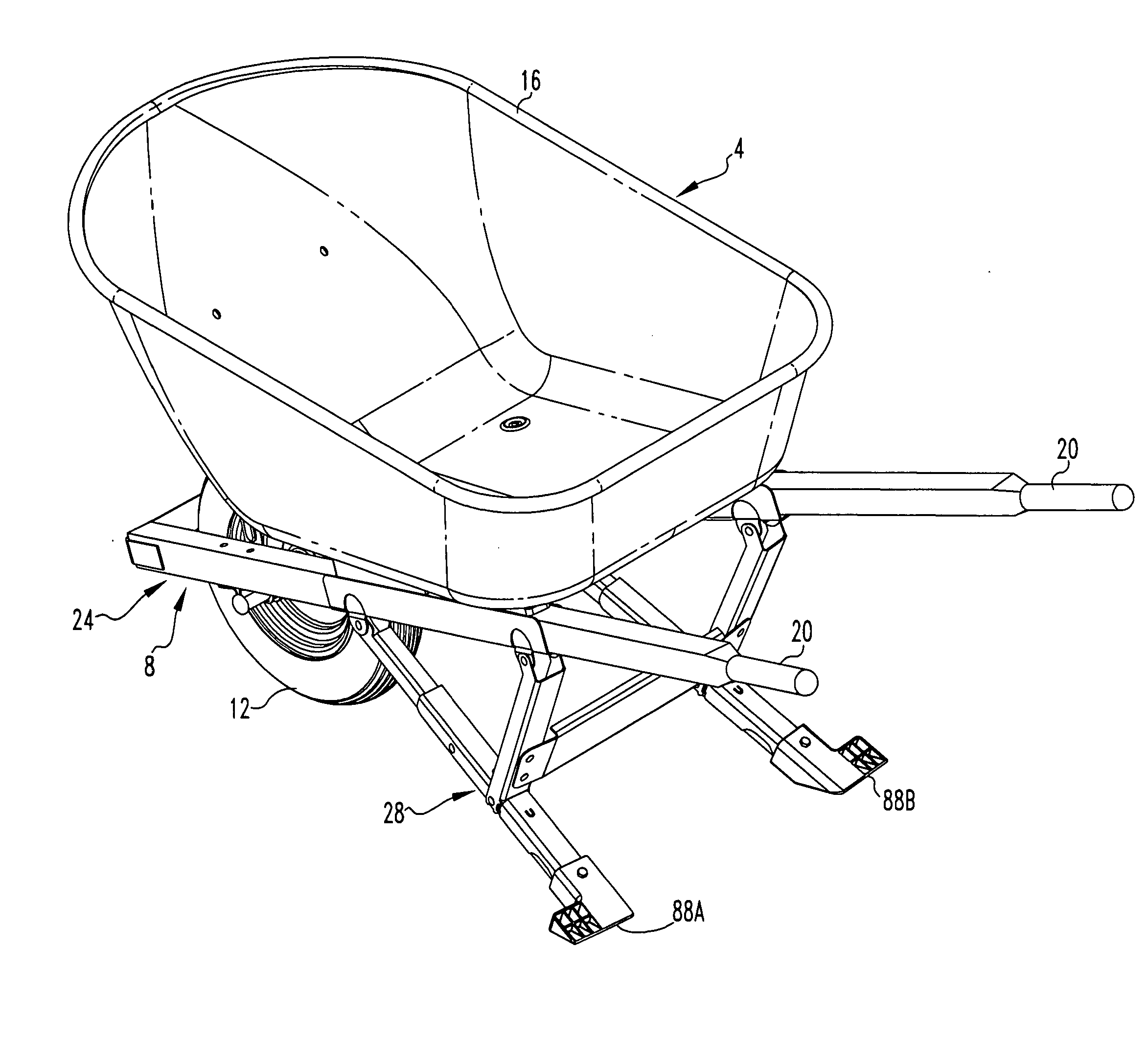
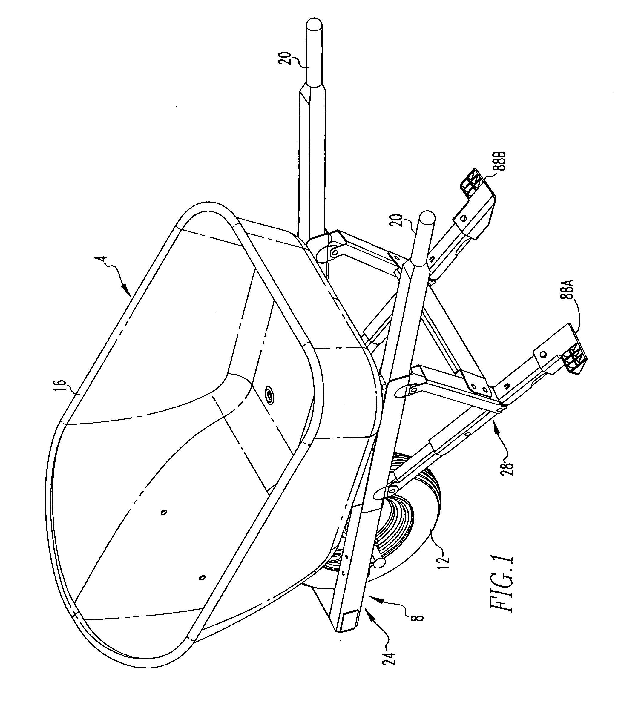
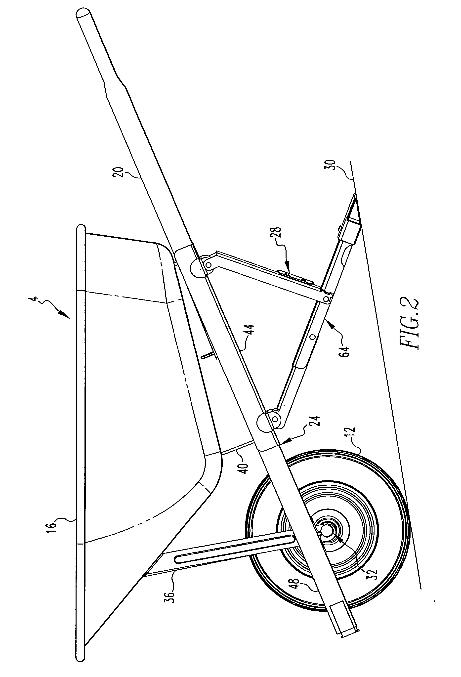
[0043] An improved wheelbarrow 4 in accordance with the present invention is indicated generally in FIGS. 1-3. The wheelbarrow 4 is advantageously configured to be collapsible, as is indicated generally in FIG. 3A, in order to occupy less space than when the wheelbarrow 4 is in a non-collapsed position, as is indicated generally in FIG. 1. The wheelbarrow 4 also is advantageously configured to be quickly assembled during initial assembly of the wheelbarrow 4 when new.

[0044] As can be seen from FIG. 3, the wheelbarrow 4 includes a frame subassembly 8, a wheel 12, a tray 16, and a pair of handles 20. The wheel 12, the tray 16, and the handles 20 are mountable to the frame subassembly 8 in order to form the assembled wheelbarrow 4. The frame assembly 8 can be advantageously manufactured and delivered to a retailer or a customer in an assembled condition as is depicted generally in FIG. 3. In order to construct the wheelbarrow 4, the wheel 12, the tray 16, and the handles 20 are mounte...


PUM


Abstract

An improved wheelbarrow includes a pair of legs that are each configured as four-bar linkages and are collapsible. Each of the legs includes an advantageously simple lock for releasably locking the leg in extended and retracted positions. The wheelbarrow includes a frame assembly, a wheel, a tray, and a pair of handles. The frame assembly can be assembled by the manufacturer, and the wheelbarrow can then be provided as a kit in accordance with the present invention that can be assembled by the retailer or the consumer by simply attaching the wheel, the tray, and the handles to the frame assembly. A support block is disclosed which facilitates assembly and strengthens the legs.

Description

CROSS-REFERENCE TO RELATED APPLICATION [0001] This application is related U.S. patent application Ser. No. 10 / 216,071, filed Aug. 9, 2002, entitled “COLLAPSIBLE WHEELBARROW AND ASSOCIATED METHOD”, the disclosures of which are incorporated herein by reference.BACKGROUND OF THE INVENTION [0002] 1. Field of the Invention [0003] The present invention relates generally to wheelbarrows and, more particularly, to a wheelbarrow having collapsible legs and also to a wheelbarrow that can be assembled relatively quickly. [0004] 2. Description of the Related Art [0005] Wheelbarrows of numerous different configurations are known in the relevant art. Wheelbarrows can be generally stated as including a tray that can receive and carry a quantity of material therein, a wheel that supports the tray and permits the tray to be moved with respect to a surface such as the grade, and at least a first handle that permits a user to apply forces to drive the tray and the wheel to desired locations. Wheelbarr...

Claims


Application Information

Patent Timeline
IPC IPC(8): B62B1/00B62B1/20
CPCB62B1/20B62B1/008
Inventor TOMCHAK, MICHAEL J.ALBERT, BARRY R.LUPEY, MIKE
Owner AMES TRUE TEMPER
Learn More