Side entry apparatus and method

a side entry and side entry technology, applied in the direction of drilling pipes, directional drilling, borehole/well accessories, etc., can solve the problems of failure of the connection and/or tool, failure of the rotary floor, and over torque of the connection, so as to prevent the overturning of the tubular, the length of the tool is shorter, and the connection is safer.

Active Publication Date: 2005-12-22
BOYD ANTHONY R
View PDF4 Cites 7 Cited by
  • Summary
  • Abstract
  • Description
  • Claims
  • Application Information

AI Technical Summary

Benefits of technology

[0016] An advantage of the present invention is that the apparatus will prevent the over torquing of a tubular. Another advantage is that the apparatus can be used as a side entry tool on a rig drilling a well. Yet another advantage is that the invention allows a significant amount of torque be applied to the apparatus without damaging the apparatus. Still yet another advantage is that the apparatus will result in safer connections since the connections will not be over torqued.
[0017] A feature of the present invention includes the splines on the body portion will engage and cooperate with splines on the bottom sub portion. Another feature is that the torque is applied only to the spline. Another feature is that multiple apertures may be provided for multiple entry points. Yet another feature is that the central passage can contain a large flow through bore. Yet another feature is the seal means contain the pressure from the well.
[0018] Another feature is that the length of the tool is shorter than prior art devices. The novel side entry device also cost less to manufacture and takes less time to manufacture. Yet another feature is that no make-up torque is required on the connections. Still yet another feature is that one embodiment has two openings, one for wireline entry, and a second for pumping. In still another embodiment, an upper part of the tool can have spline means for transferring torque and the lower part of the tool may comprise means for allowing rotation of the lower part of the tubular string.

Problems solved by technology

However, in the course of applying the torque, some connections may become over torqued.
As understood by those of ordinary skill in the art, the application of too much torque can cause damage to the threads, tubular and / or tool, which in turn may lead to failure of the connection and / or tool.
The failure may occur at the rotary floor.
These types of failures may result in catastrophic effects such as a blowout of the well.

Method used


Image

  • Side entry apparatus and method
  • Side entry apparatus and method
  • Side entry apparatus and method

Examples


third embodiment

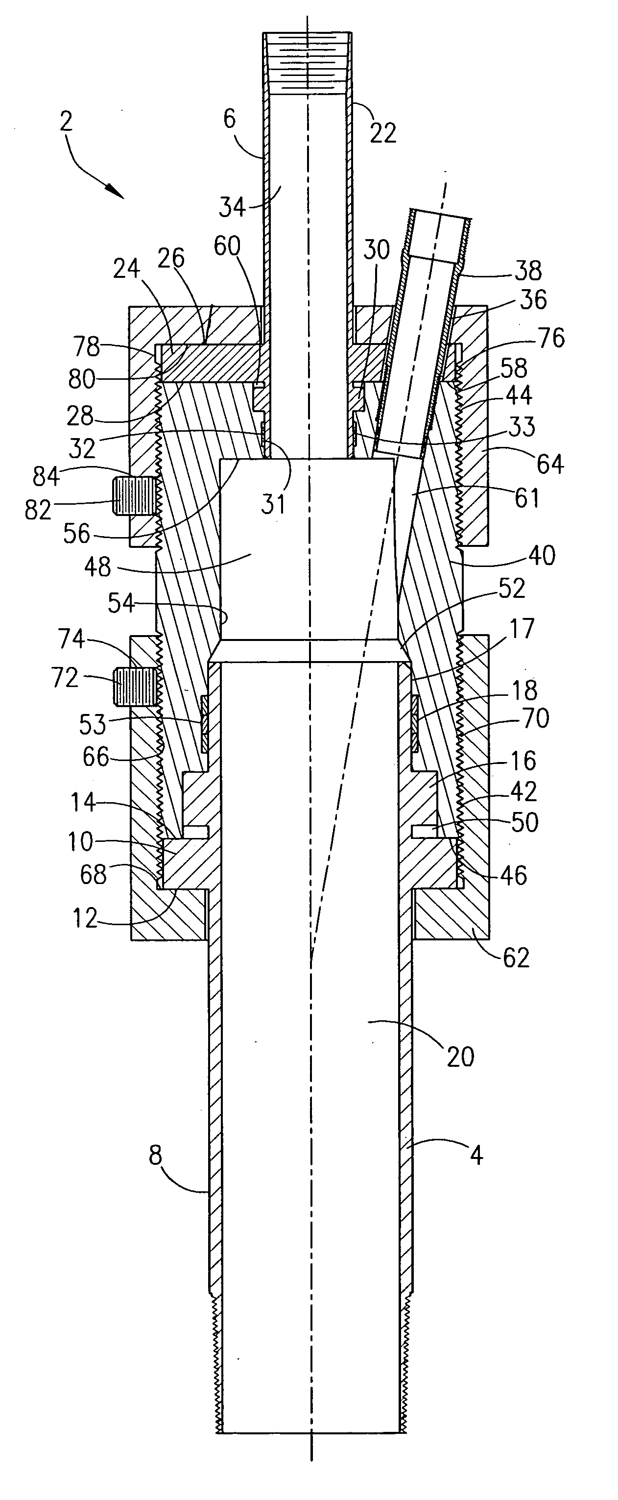
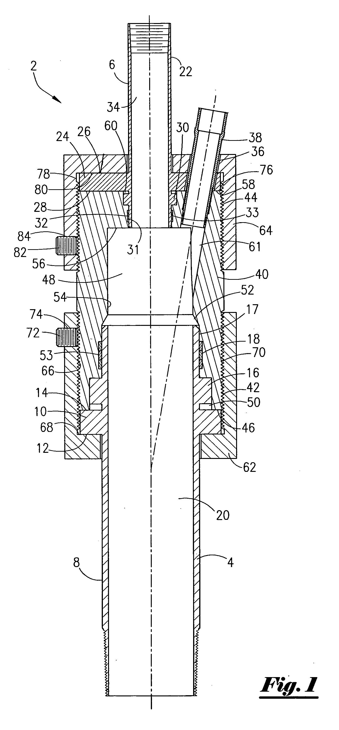
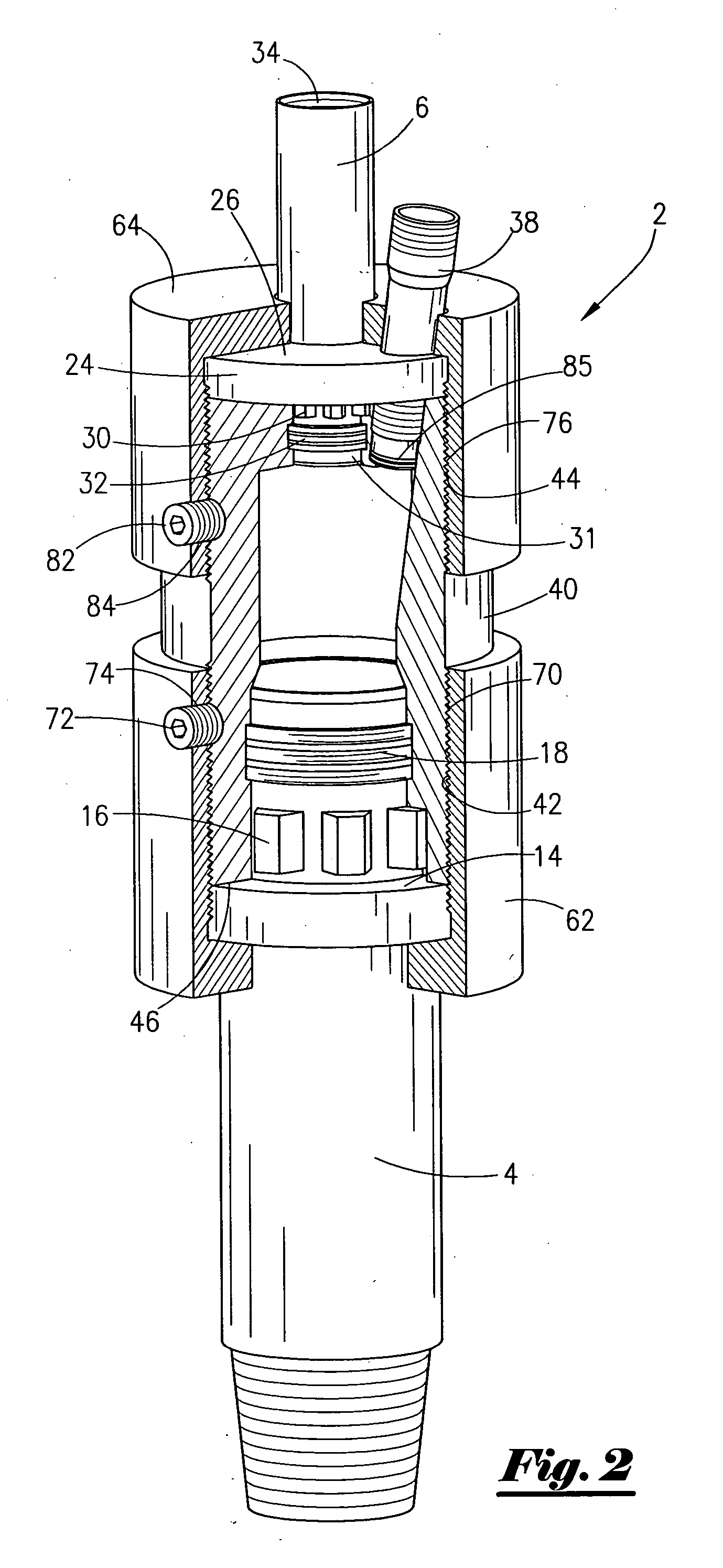
[0038] Referring now to FIG. 5, a cross sectional view of the present invention. The apparatus 104 includes a top sub 106 that contains a radial shoulder 108 that then extends to a plurality of splines 110, and concludes with a seal bore 111 that cooperates with seal mean means 112, and wherein the seal means 112 are contained within an indentation 113 on mandrel 124. The top sub 106 has an internal bore 114. The apparatus 104 also contains a bottom lubricator 116, and wherein the bottom lubricator 116 has a radial shoulder 118 that extends to a plurality of splines 120. From the plurality of splines 120, the bottom lubricator 116 has a seal bore 121 that cooperates with seal means 122 located within an indentation in mandrel 124.

[0039] The apparatus 104 includes a mandrel 124, and wherein the mandrel 124 is generally cylindrical. The mandrel 124 contains a top neck portion, seen generally at 126. The top neck portion 126 contains external threads 128 that in turn extends to shoulde...

fourth embodiment

[0047] Referring now to FIG. 8, a cross-sectional view of the side entry tool 198 will now be described. As noted earlier, like numerals appearing in the various figures refer to like components. In this embodiment, the bottom sub 4, sometimes referred to as the lubricator sub 4, contains a top outer portion 200 that extends to a radial shoulder 202 which in turn extends to the bottom sub 4. The cap 62 is provided, and wherein the cap 62 is threadedly attached to the mandrel 40 as previously described. In the preferred embodiment, the cap 64 may be of a “right-handed” thread make-up, while the cap 62 will be the “left-handed” thread make-up due to the side entry tool 198 swiveling nature.

[0048] As seen in FIG. 8, the rotating means for allowing the rotation of the bottom sub 4, relative to the cap 64 and top sub 6, is positioned below the radial shoulder 202. In one preferred embodiment, the rotating means consist of a first disc 204, a series of roller bearings 206, and a second di...


PUM


Abstract

An apparatus and method for transferring torque on a rig. The apparatus comprises a central body having a central passage, and a first plurality of splines formed within the central passage and a second plurality of splines formed on a bottom sub, and wherein the first plurality of splines and the second plurality of splines cooperate to engage and transfer the torque applied to the central body. A third plurality of splines may be formed within the central passage, and a fourth plurality of splines formed on a top sub may be included that cooperates to engage and transfer the torque applied to the cental body with the third plurality of splines. In one of the preferred embodiments, the top sub is connected to a top drive of a rig. The apparatus may further comprise a first threaded cap engaging that contains an opening in communication with the central passage. A wireline is disposed within the opening.

Description

BACKGROUND OF THE INVENTION [0001] This invention relates to a side entry apparatus. More particularly, but not by way of limitation, this invention relates to a side entry apparatus used to channel wireline into a well and a method of use. [0002] During the exploration, drilling, completion and production of hydrocarbons, operators find it necessary to perform wireline work within the well. In most instances, an operator will rig up a lubricator, and wherein the lubricator is attached to the well head. The lubricator is a tubular member that contains a central passage for the conveyance of other concentric tubulars, wireline, electric line, braided line, drilling fluids, completion fluids, etc. The lubricator may contain certain devices such as valves, blow out preventor stacks, swivels, etc. as is well understood by those of ordinary skill in the art. [0003] U.S. Pat. No. RE 33,150 to Boyd describes a side entry tool and is incorporated herein by reference. The side entry tool is ...

Claims


Application Information

Patent Timeline
Patent Type & Authority Applications(United States)
IPC IPC(8): E21B17/02E21B19/16
CPCE21B17/025
Inventor BOYD, ANTHONY R.
Owner BOYD ANTHONY R
Why Eureka
Try Eureka