System and method for generating generalized displacement maps from mesostructure geometries

a geometries and generalization technology, applied in the field of automatic texture mapping, can solve the problems of inability to realistically render silhouettes and the effects of surface curvature, inability to handle arbitrary non-height-field mesostructures, and inability to compute texture coordinates. to achieve the effect of facilitating texture coordinate computation

Inactive Publication Date: 2005-12-22
MICROSOFT TECH LICENSING LLC
View PDF1 Cites 16 Cited by
  • Summary
  • Abstract
  • Description
  • Claims
  • Application Information

AI Technical Summary

Benefits of technology

[0019] A “mesostructure renderer,” as described herein operates to solve the problems of existing mesostructure rendering techniques through the use of a pre-computed multi-dimensional “generalized displacement map” (GDM). The GDM then is used to provide real-time rendering of highly detailed non-height-field mesostructures for rendering the mesostructure textures onto open or closed surfaces of arbitrary geometry. Further, it should be noted that any height-field mesostructure can also be represented as a non-height-field mesostructure. In rendering the mesostructures, the pre-computed GDM values facilitate texture coordinate computation of viewing rays whose piece-wise linear trajectory in texture space is determined in object space according to the shape of a base mesh upon which the mesostructure texture is to be rendered. Further, the GDM-based approach described herein overcomes both the texture distortion problems of conventional view-dependent displacement mapping (VDM) techniques and the computational expense of directly mapped mesostructure geometry by pre-computing mesostructure visibility jointly in texture space and object space.
[0022] The GDM is then used to determine intersections with the mesostructure geometry for each ray segment in texture space. Once these intersections with mesostructure geometry have been determined, the mesostructure renderer then renders visible mesostructure pixels for the surface of the object model by using texture information provided by the intersections with the mesostructure geometry for each ray segment in texture space. In one embodiment, rendering of the textured surface of the object model is performed as a real-time per-pixel operation using programmable graphics hardware to further accelerate mesostructure rendering on the target surface. In a related embodiment, further acceleration of mesostructure rendering is accomplished by providing a user adjustable threshold for allowable texture distortion. As the allowable distortion threshold is increased, the number of rendered triangles decreases, thereby resulting in a significant increase in overall frame rate.
[0023] In addition, by accounting for curvature variations and texture warping in object space, ray intersections in texture space are more accurately established, resulting in less texture distortion. The GDM approach of the mesostructure renderer is also useful for quickly determining whether any intersection point is shadowed from local illumination. Similarly, the GDM approach of the mesostructure renderer is also applicable for use in rendering scenes with global illumination.

Problems solved by technology

Unfortunately, because BTFs are merely 2-D images of mesostructure samples, those samples do not typically contain any 3-D geometric information.
Consequently, silhouettes and the effects of surface curvature cannot typically be realistically rendered.
Unfortunately, because such models tend to be highly detailed, mapping mesostructures to such models is typically very computationally expensive.
Consequently, such techniques are typically unable to handle arbitrary non-height-field mesostructures as discussed below.
Unfortunately, conventional VDM schemes have at least two significant drawbacks.
First, VDM is applicable to height-field geometry on closed surfaces, and provides poor quality results, at best, on open surfaces.
Second, due to a large computational overhead, VDM can be practically pre-computed for only a limited class of surface shapes, such as those having a single surface curvature parameter.
As a result, the pre-computed VDM lacks the specificity to accurately represent surfaces with curvature variations and texture warping.
As a result, VDM textured surfaces can often exhibit significant texture distortions in the synthesized textures.
Unfortunately, for non-diffuse surfaces, this approach models only a fixed viewpoint.
However, although these image-based representations are capable of capturing the true appearances of a general mesostructure sample, the 2-D geometric structure inherent in simple images of mesostructures precludes the rendering of mesostructure silhouettes.
Unfortunately, these schemes do not account for silhouettes.
However, while techniques based on height field geometries benefit from relative ease in processing, they typically lack the generality to describe a range of surface geometries that includes weave patterns and slanted protrusions.
Unfortunately, such methods are computationally expensive and do not typically translate well to real-time applications.
Unfortunately, in each of these slice-based methods, the number of slices used for each triangle increases with volumetric resolution.
As a result, the computational overhead necessary for rendering such textures is further magnified when sophisticated per-pixel shading is incorporated.
As a result, such schemes do not appear to be capable of rendering volumetric textures with global illumination in real-time using conventional computing techniques.
However, the problem with rendering of silhouettes is not adequately addressed by such schemes so as to provide for real-time rendering.
As the allowable distortion threshold is increased, the number of rendered triangles decreases, thereby resulting in a significant increase in overall frame rate.

Method used


Image

  • System and method for generating generalized displacement maps from mesostructure geometries
  • System and method for generating generalized displacement maps from mesostructure geometries
  • System and method for generating generalized displacement maps from mesostructure geometries

Examples


Embodiment Construction

[0042] In the following description of the preferred embodiments of the present invention, reference is made to the accompanying drawings, which form a part hereof, and in which is shown by way of illustration specific embodiments in which the invention may be practiced. It is understood that other embodiments may be utilized and structural changes may be made without departing from the scope of the present invention.

1.0 Exemplary Operating Environment:

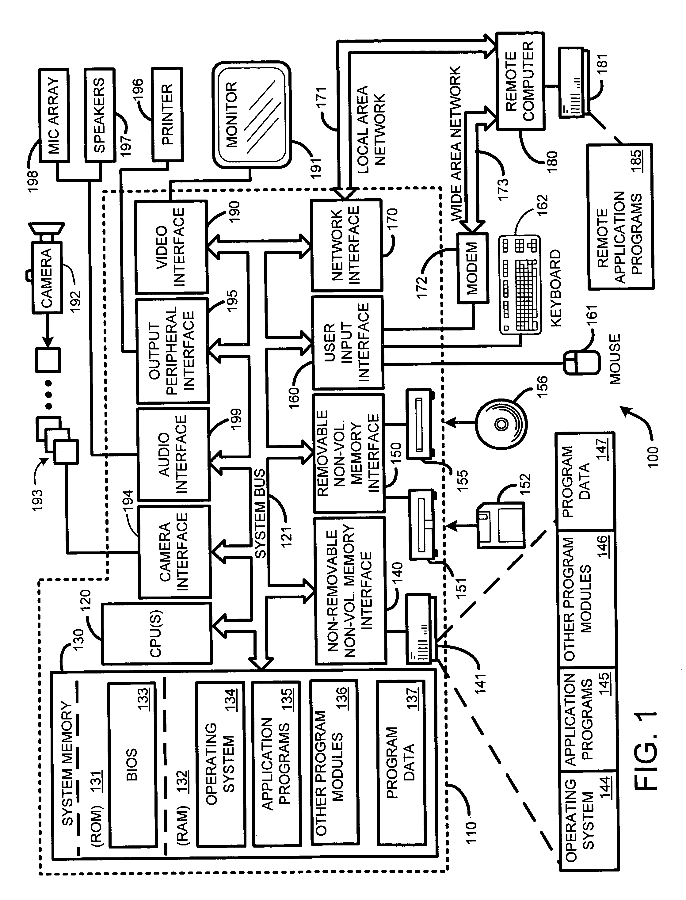
[0043]FIG. 1 illustrates an example of a suitable computing system environment 100 on which the invention may be implemented. The computing system environment 100 is only one example of a suitable computing environment and is not intended to suggest any limitation as to the scope of use or functionality of the invention. Neither should the computing environment 100 be interpreted as having any dependency or requirement relating to any one or combination of components illustrated in the exemplary operating environment 100.

[0044] Th...


PUM


Abstract

A “mesostructure renderer” uses pre-computed multi-dimensional “generalized displacement maps” (GDM) to provide real-time rendering of general non-height-field mesostructures on both open and closed surfaces of arbitrary geometry. In general, the GDM represents the distance to solid mesostructure along any ray cast from any point within a volumetric sample. Given the pre-computed GDM, the mesostructure renderer then computes mesostructure visibility jointly in object space and texture space, thereby enabling both control of texture distortion and efficient computation of texture coordinates and shadowing. Further, in one embodiment, the mesostructure renderer uses the GDM to render mesostructures with either local or global illumination as a per-pixel process using conventional computer graphics hardware to accelerate the real-time rendering of the mesostructures. Further acceleration of mesostructure rendering is achieved in another embodiment by automatically reducing the number of triangles in the rendering pipeline according to a user-specified threshold for acceptable texture distortion.

Description

CROSS REFERENCE TO RELATED APPLICATIONS [0001] This application is a Divisional Application of U.S. patent application Ser. No. 10 / 965,603, filed on Oct. 13, 2004, by Wang, et al., and entitled “REAL-TIME TEXTURE RENDERING USING GENERALIZED DISPLACEMENT MAPS,” and claims the benefit of that prior application under Title 35, U.S. Code, Section 120. [0002] This application also claims the benefit under Title 35, U.S. Code, Section 119(e), of a previously filed U.S. Provisional Patent Application Ser. No. 60 / 580,780 filed on Jun. 18, 2004, by Wang, et al., and entitled “REAL-TIME TEXTURE RENDERING USING GENERALIZED DISPLACEMENT MAPS.BACKGROUND [0003] 1. Technical Field [0004] The invention is related to automatic texture mapping, and in particular, to a system and method for computing generalized displacement maps (GDM) from arbitrary mesostructure geometries for use in real-time rendering of arbitrary non-height-field mesostructures for open or closed surfaces of arbitrary geometry. [...

Claims


Application Information

Patent Timeline
Patent Type & Authority Applications(United States)
IPC IPC(8): G06T15/20G06T15/50G06T15/60G06T17/00G09G5/00
CPCG06T15/04
Inventor WANG, XITONG, XINLIN, STEPHENGUO, BAININGSHUM, HEUNG-YEUNG
Owner MICROSOFT TECH LICENSING LLC
Why Eureka
Try Eureka