Distributed printing control apparatus and print job distribution method

Inactive Publication Date: 2005-12-22
SEIKO EPSON CORP
View PDF5 Cites 20 Cited by
  • Summary
  • Abstract
  • Description
  • Claims
  • Application Information

AI Technical Summary

Benefits of technology

[0141] In the printing system of this embodiment described above, the printer PRT1 having the distributed printing control functions overwrites the head number file Fb with a next ordinal number subsequent to the ordinal number of the previously specified distribution destination printer. In a next cycle of the printer specification process, the printer PRT1 determines whether the printer corresponding to the ordinal number currently written in the head number file Fb is included in the printers extracted as the possible options for the distribution destination printer. When the corresponding printer is not included in the extracted possible options, the printer PRT1 sequentially reads out the given ordinal numbers to the last, which is identical with the ordinal number of the previously specified distribution destination printer, and repeats the determination.
[0142] The procedure of this embodiment thus effectively lowers the potential that an identical printer is consecutively specified as the distribution destination printer. This arrangement desirably prevents inefficient concentration of print jobs on one particular printer and completes printing in a short time period.
[0143] The printer PRT1 extracts the possible options for the distribution destination printer among the printers with the IP addresses included in the distribution destination specification file Fa. Namely the distribution destination specification file Fa informs the printer PRT1 of the user's desired printers for the distribution destination printer.
[0144] The printer PRT1 makes an inquiry about the model name to the devices with the specified IP addresses, prior to the final specification of the distribution destination printer. Based o

Problems solved by technology

This undesirably concentrates print jobs on one particular prin

Method used


Image

  • Distributed printing control apparatus and print job distribution method
  • Distributed printing control apparatus and print job distribution method
  • Distributed printing control apparatus and print job distribution method

Examples


first embodiment

A. First Embodiment

A1. System Configuration

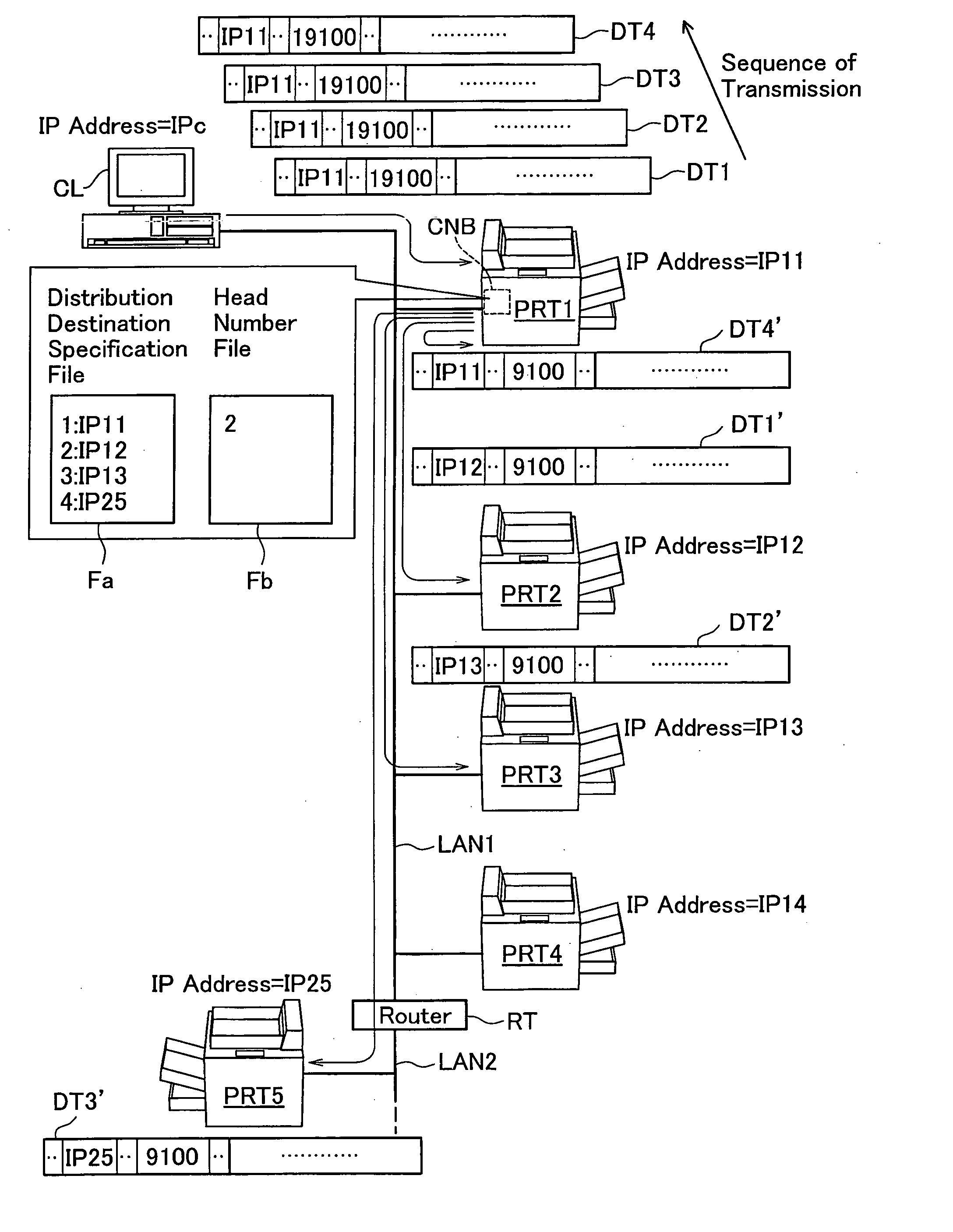
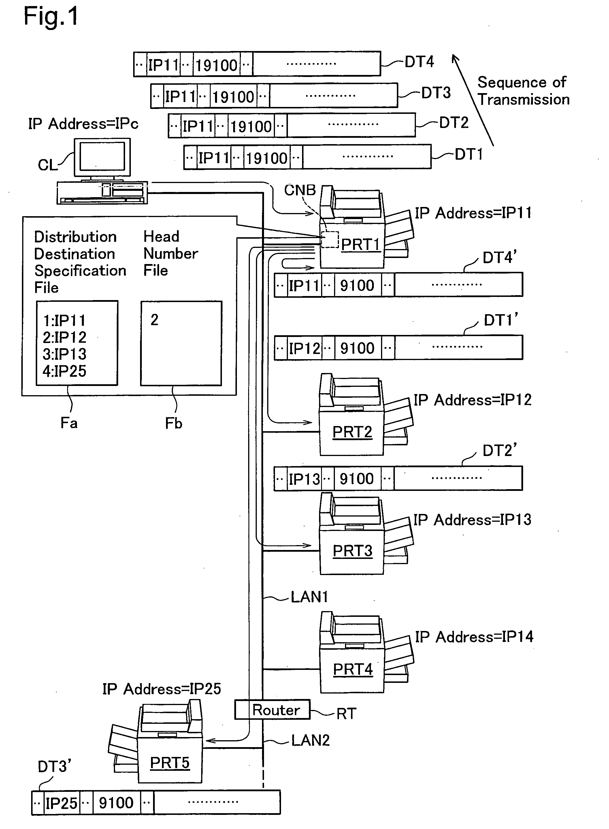
[0057]FIG. 1 schematically illustrates the configuration of a printing system including a printer PRT1 in a first embodiment of the invention. As illustrated, this printing system includes a client PC (hereafter referred to as the client) CL and multiple printers PRT1 to PRT5. The client CL and the printers PRT1 to PRT4 are connected to one local area network LAN1, and the printer PRT5 is connected to another local area network LAN2. The two local area networks LAN1 and LAN2 are interconnected via a router RT.

[0058] Communication between the respective devices basically follows the TCP / IP protocol, and fixed IP addresses are allocated to the respective devices. For convenience of explanation, it is assumed that fixed IP addresses ‘IPc’, ‘IP11’ to ‘IP14’, and ‘IP25’ are respectively allocated to the client CL, to the printers PRT1 to PRT4, and to the printer PRT5. Strictly speaking, these IP addresses are not set directly in the client CL ...

second embodiment

B. Second Embodiment

[0145] The technique of the first embodiment uses the identical printing protocol (non-procedural protocol) but different port numbers (the general number ‘9100’ and the particular number ‘19100’) in the process of sending print jobs from the client CL to the printer PRT1 having the distributed printing control functions and in the process of sending the print jobs from the printer PRT1 to the specified distribution destination printers to achieve distributed printing. The technique of a second embodiment uses different printing protocols in the process of sending print jobs from the client CL to the printer PRT1 having the distributed printing control functions and in the process of sending the print jobs from the printer PRT1 to the specified distribution destination printers to achieve distributed printing.

B1. Structure of Printer

[0146]FIG. 10 mainly shows the structure of the printer PRT1 in the second embodiment of the invention. The structure of the print...

modified example 1

C1. Modified Example 1

[0163] In the first and the second embodiments discussed above, the head number file Fb includes a next ordinal number subsequent to the ordinal number of the previously specified distribution destination printer. The head number file may otherwise include the ordinal number of the previously specified distribution destination printer. In this modified structure, the parent task processing module 23 determines whether the printers extracted as the possible options for the distribution destination printer include a printer corresponding to a next ordinal number subsequent to the ordinal number written in the head number file Fb at step S312 in the flowchart of FIG. 8.

[0164] As long as the parent task processing module 23 can check the previously specified distribution destination printer, the ordinal number written in the head number file may be replaced by any other suitable piece of information for identifying the previously specified distribution destination...


PUM


Abstract

A distributed printing control apparatus of the invention includes a storage module that stores identification information for identifying at least a previous distribution destination printing device, and a control module. On reception of a print job sent under a preset condition, the control module specifies a current distribution destination printing device based on the identification information, among residual printing devices other than the previous distribution destination printing device, sends the received print job to the specified current distribution destination printing device, and stores information for identifying the specified current distribution destination printing device as the identification information into the storage module. The technique of the invention distributes multiple print jobs to multiple printing devices under the policy of restricting specification of an identical printing device for consecutive distribution of sequential print jobs. This arrangement desirably prevents inefficient concentration of print jobs on one particular printing device and completes printing in a short time period.

Description

BACKGROUND OF THE INVENTION [0001] 1. Field of the Invention [0002] The present invention relates to a technique of distributing print jobs to two or more printing devices connected to a network to attain distributed printing. More specifically the technique of the invention restricts specification of an identical printer for consecutive distribution of sequential print jobs. [0003] 2. Description of the Related Art [0004] A printing system including multiple printers connected to an identical network has been widespread to enable each user to selectively use the multiple printers. A distributed printing technique has been proposed to distribute multiple print jobs to multiple printers for parallel printing and thereby complete printing in a short time period (see, for example, Japanese Patent Laid-Open Gazette No. 2002-215368). [0005] In the prior art printing system that distributes multiple print jobs to multiple printers, the printer specified as the previous distribution destin...

Claims


Application Information

Patent Timeline
IPC IPC(8): G06F3/12B41J29/38G06F15/00
CPCH04N1/00954H04N1/32523H04N1/32502
Inventor SHIMA, TOSHIHIROTANIGUCHI, SHINYA
Owner SEIKO EPSON CORP
Why Eureka
Try Eureka