
Illuminating device for display device

a technology of illumination device and display device, which is applied in the direction of lighting support device, lighting and heating apparatus, instruments, etc., can solve the problems of increased heat generation, increased power consumption, and increased power consumption, so as to reduce the luminance or luminance unevenness, prevent uneven luminance on information display surface, and excellent display quality

Inactive Publication Date: 2005-12-22
SHARP KK
View PDF17 Cites 23 Cited by
  • Summary
  • Abstract
  • Description
  • Claims
  • Application Information

AI Technical Summary

Benefits of technology

[0013] The present invention was made in view of the above problems, and it is an object of the present invention to provide an illuminating device for a display device in which unevenness of luminance on an information display surface is prevented by securing a position accuracy of a light source lamp, light leakage from a lamp supporting member, lower luminance or unevenness of luminance is reduced, and excellent display quality may be provided, a lamp supporting member, and a liquid crystal display device comprising the illuminating device for a display device.
[0014] While the inventors of the present invention have studied various kinds of illuminating device for a display devices which may be preferably applied to a backlight and the like of the liquid crystal display device and may implement a large backlight having high luminance, they focused on a constitution in which a light source lamp is supported by a lamp supporting member and fixed to a back light angle (frame) to be mounted on the device, for example, a constitution which is formed in a segmented gripping shape having an opening in one part and made of a transparent material having flexibility as shown in FIG. 5A. In this case, it is found that since the fixing pin (pin for fixing lamp) 12 is provided just under a structural part for gripping the light source lamp 21, and the fixing pin 12 is inserted into holes of the reflector 112 and the backlight angle 111 to fix the light source lamp 21, light from the light source lamp 21 leaks from (1) the pin part and (2) a gap between the pin part and the hole, which adversely affects the display quality. That is, when the lower part (the part for fixing the lamp supporting member in the display by engaging with the backlight angle) is provided substantially just under the upper part of the lamp supporting member 11 (the part for gripping the light source lamp), a dark area caused by the light leakage from the position of the fixing pin is observed as shown in FIG. 5B, which causes the display quality to be lowered by the influence of the luminance unevenness because of the light leakage.
[0015] Thus, for example, when the fixing pin 12 of the lamp supporting member 11 is provided at a position other than a position just under the light source lamp 21, it is found that the light source lamp 21 is protected, unevenness of luminance on the information display surface is prevented by securing a position precision of the light source lamp 21, a level of the dark area caused by the light leaking due to the structure of the lamp supporting member 11 is decreased, the influence of the unevenness of luminance is sufficiently reduced and preferable display quality is provided, so that the above problems can be admirably solved. In addition, when the lamp supporting member 11 is formed of a reflective material, that is, when reflecting coefficient of the lamp supporting member 11 is increased by providing reflecting coating on the lamp supporting member 11 or forming the lamp supporting member 11 from high-reflective material, it is found that the operation and effect of the present invention can be sufficiently provided, thereby to attain the present invention.

Problems solved by technology

In addition, power consumption is large and the total amount of heat generation is increased.
In these devices, lower luminance and luminance unevenness are posed due to the structure of the lamp holder.
For example, when the amount of light is small at the time of carrying out gradation display or starting the display, the luminance unevenness is likely to become conspicuous, and therefore improvement in that point is needed.

Method used


Image

  • Illuminating device for display device
  • Illuminating device for display device
  • Illuminating device for display device

Examples


embodiment 1

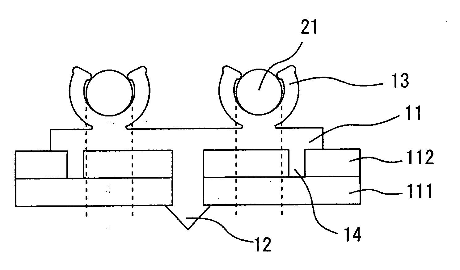
[0096] In a liquid crystal display device having an illuminating device behind a liquid crystal display element, a white lamp supporting member which has a configuration for being able to support a fluorescent tube and is formed of insulation resin, is provided on high reflective resin of a display region, whereby the illuminating device in which the fluorescent tubes are arranged in parallel and equally spaced is constituted. In FIG. 1, the lamp supporting member 11 has the two structural parts for gripping the light source lamps 21 and the fixing pin 12 provided in the middle position thereof so that the fixing pin 12 is provided apart from a position just under the light source lamp 21. In this case, the pin 14 for controlling a position of the lamp supporting member 11 is provided at one or both ends of the lamp supporting member 11.

[0097] According to this constitution, a defect caused by light leakage may be prevented, and displacement of the lamp may be controlled. Also sinc...

embodiment 2

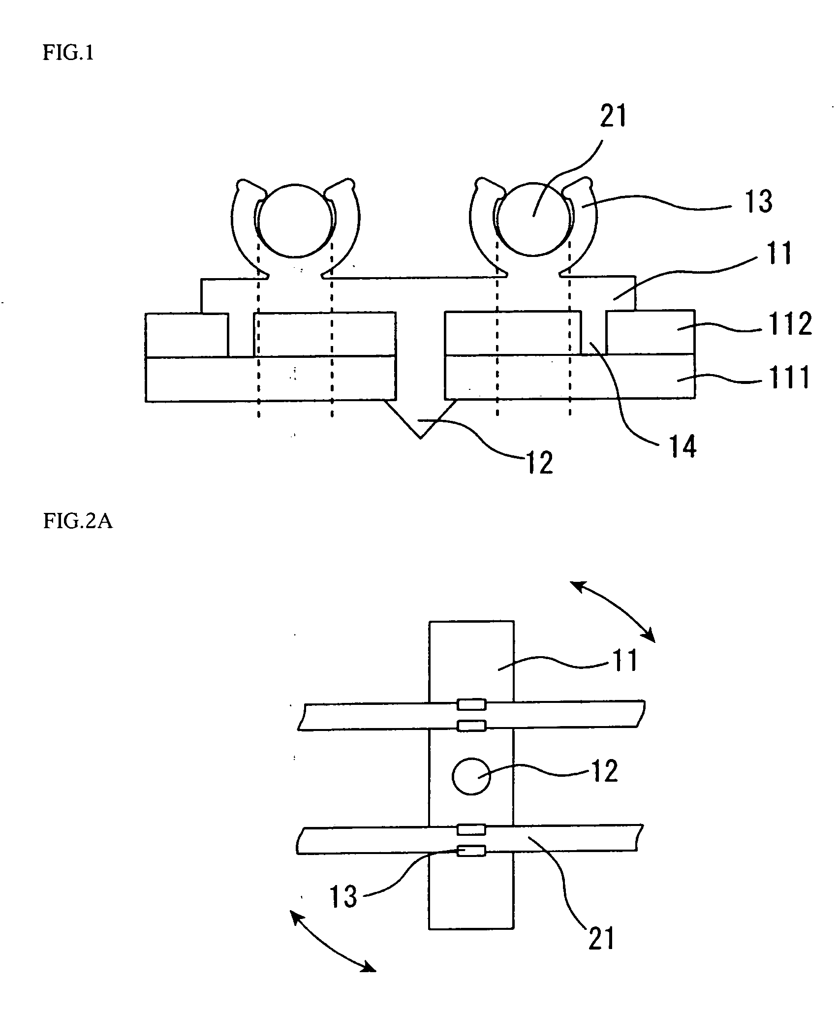
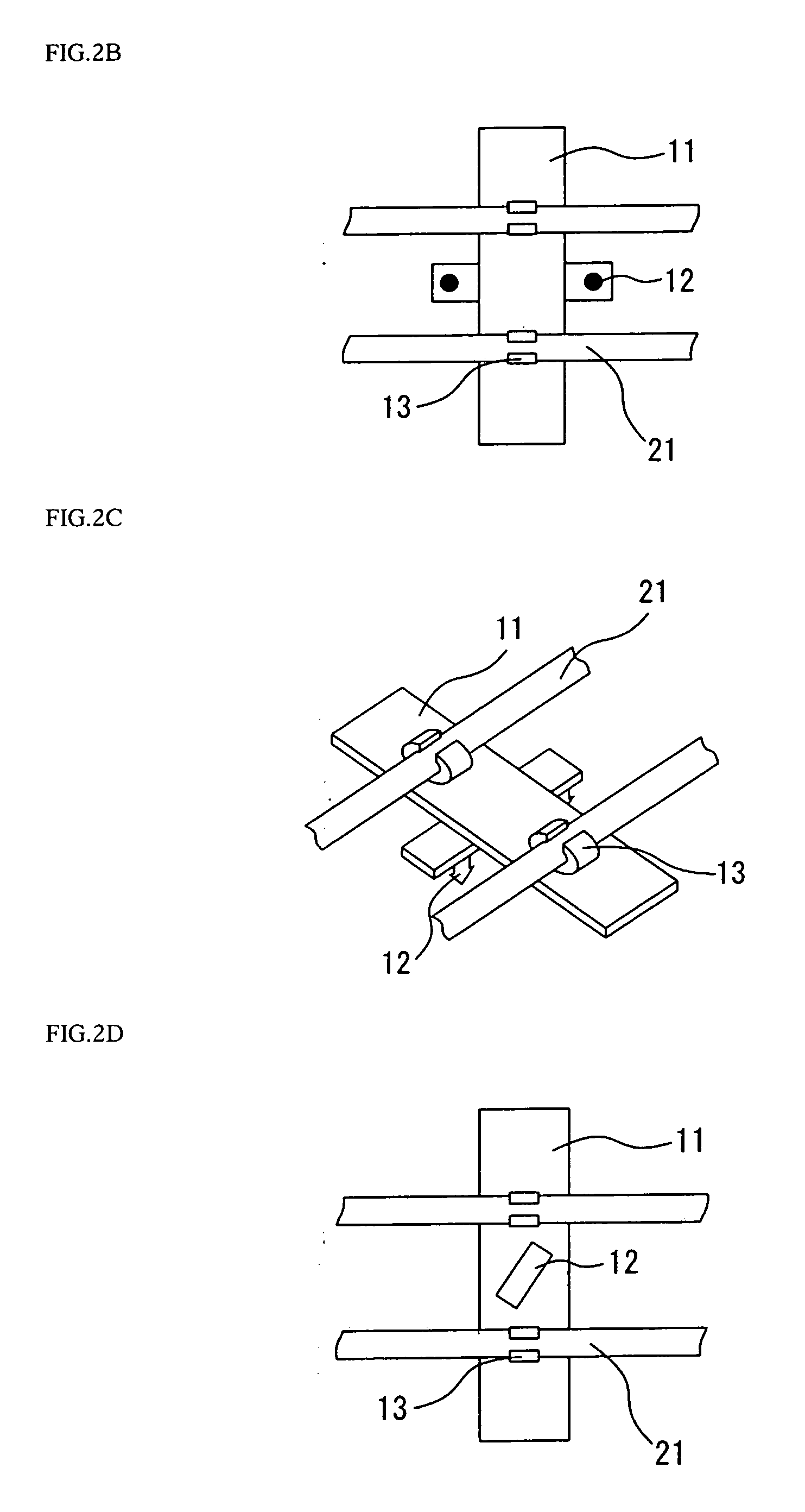
[0099] Similar to Embodiment 1, display region of an illuminating device is constituted using a lamp supporting member. FIGS. 2A to 2D show the lamp supporting member 11 having two structural parts 13 for gripping the light source lamps 21 and the fixing pin 12 provided in the middle position thereof. In FIG. 2A, the fixing pin 12 has a round shape, and In FIG. 2B, the fixing pins 12 have a round shape and the member having two or more fixing pins 12 are provided in the middle position of the lamp supporting member 11, whereby the lamp supporting member 11 is fixed. FIG. 2C is a perspective view showing the lamp supporting member in FIG. 2B. In FIG. 2D, the fixing pin 12 having a rectangular shape and the length direction of the rectangular shape is in an oblique direction to the length direction of the light source lamp 21.

[0100] According to these constitutions, a defect caused by light leakage may be prevented, and since the structural parts of lamp supporting member grip the li...

embodiment 3

[0101] Similar to Embodiment 1, display region of an illuminating device is constituted using a lamp supporting member. As shown in FIG. 3, the lamp supporting member 11 has two structural parts 13 for gripping the light source lamps 21 and has the fixing pin 12 and the pin 15 for supporting a diffuser in the middle position thereof. In this case, the fixing pin 12 is arranged just under the pin 15 for supporting a diffuser.

[0102] According to this constitution, the fixing pin is provided apart from a position just under the light source lamp, and light leakage from the fixing pin may be further reduced by reflection of the pin for supporting a diffuser. Also since the structural parts of lamp supporting member grip the light source lamp, the number of parts may be reduced, therefore a stable liquid module having excellent display quality may be provided at low cost.


PUM

PropertyMeasurementUnit
transparentaaaaaaaaaa
lengthaaaaaaaaaa
angular shapeaaaaaaaaaa

Abstract

The present invention provides an illuminating device for a display device in which unevenness of luminance on an information display surface is prevented by securing a position accuracy of a light source lamp, light leakage from a lamp supporting member, lower luminance or unevenness of luminance is reduced, and excellent display quality may be provided. The illuminating device for a display device, of the present invention is an illuminating device for a display device, the illuminating device comprising a light source lamp and a lamp supporting member and having (1) A configuration in which the lamp supporting member comprises a fixing pin provided at a position other than a position substantially just under the light source lamp, (2) A configuration in which the lamp supporting member is formed of a reflective material, or a configuration in which the above-mentioned configurations are combined.

Description

REFERENCE TO RELATED APPLICATION [0001] The Nonprovisional application claims priority under 35 U.S.C. § 119(a) on Patent Application No. 2004-181370 filed in Japan on Jun. 18, 2004, and the entire contents of which are hereby incorporated in the present application by reference. BACKGROUND OF THE INVENTION [0002] 1. Field of the Invention [0003] The present invention relates to an illuminating device for a display device, a lamp supporting member and a liquid crystal display device. More particularly, it relates to an illuminating device for a display device suitable for constituting a backlight of a transparent liquid crystal display device or semi-transparent one having a transparent region in a liquid crystal display element, a lamp supporting member which is used in the illuminating device for a display device, and a liquid crystal display device comprising the illuminating device for a display device. [0004] 2. Description of the Related Art [0005] An illuminating device for a...

Claims


Application Information

Patent Timeline
Patent Type & Authority Applications(United States)
IPC IPC(8): F21V8/00F21V19/00G02F1/1335G02F1/13357
CPCF21V19/009G02F2201/465G02F1/133608G02F1/133604
Inventor MURAKAMI, YOSHIHIROONO, SATOSHI
Owner SHARP KK
Features
  • Generate Ideas
  • Intellectual Property
  • Life Sciences
  • Materials
  • Tech Scout
  • Unparalleled Data Quality
  • Higher Quality Content
  • 60% Fewer Hallucinations
Learn More