
Air injector having dental mirror mount

a technology of air injector and dental mirror, which is applied in the field of air injector with dental mirror mount, can solve the problems of not allowing individual manipulation of dental mirror, affecting the effect of patient comfort, and most combinations are complex,

Inactive Publication Date: 2005-12-22
KWONG WILLIAM K +1
View PDF18 Cites 9 Cited by
  • Summary
  • Abstract
  • Description
  • Claims
  • Application Information

AI Technical Summary

Benefits of technology

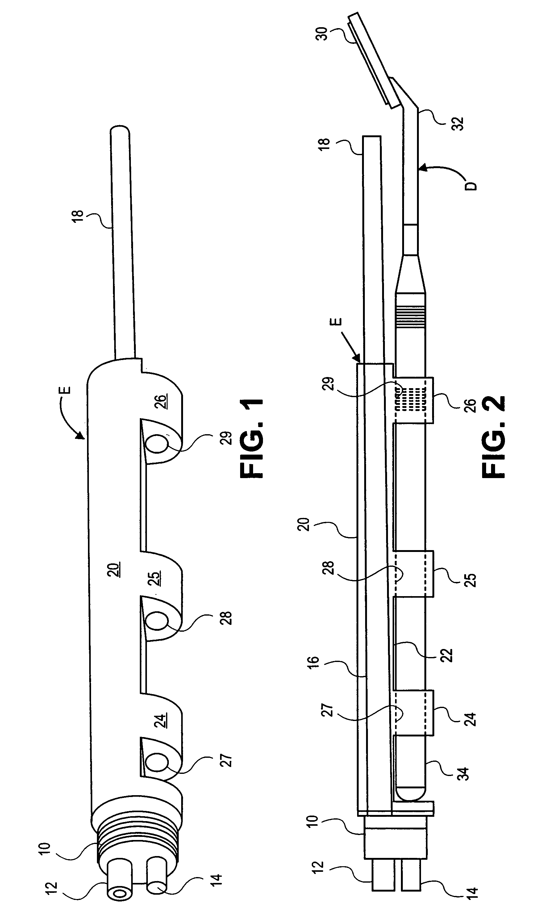
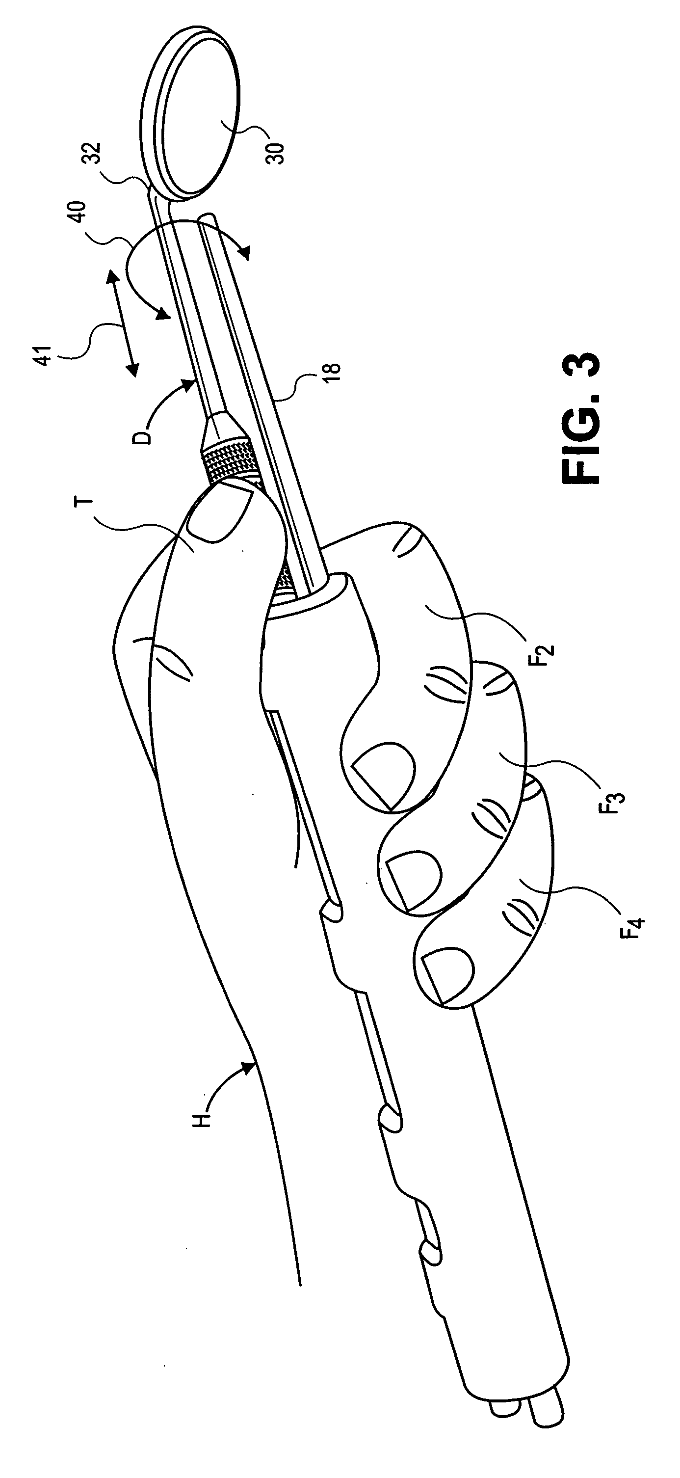
[0011] An air ejector and a dental mirror combination provide optimum view of human dentition during dental surgery. The air ejector includes a base having an air inlet, an air ejector for receiving air from the air inlet on the base and confining air flow to an air discharge for directing impingement of discharged air upon a mirror surface remote from the base. The air ejector further includes a mirror mounting body attached to the base at one end and extending around the air ejector from the base toward the air discharge. The mirror mounting body also defines a plurality of aligned spaced apart protrusions offset from the air ejector. The aligned spaced apart protrusions have aligned bores passing through the aligned spaced apart protrusions for receiving the handle of a dental mirror and aligning the handle generally parallel to the air ejector with portions of the mirror handle being exposed between the spaced apart protrusions. The air ejector is used in combination with a dental mirror. The dental mirror includes a linear handle for grasping by the hand at one end and extends away from the hand at an opposite end. An angled mirror is supported from the linear handle at the opposite end for providing a view of human dentition during dental surgery. The dental mirror handle is placed within the aligned bores at the aligned spaced apart protrusions for disposing the mirror at the air discharge of the air ejector. The mirror mounting body between the aligned spaced apart protrusions defines spatial intervals along the length of the mirror handle to permit relative mirror manipulation with respect to the air discharge. Grasping of the mirror mounting body with the hand enables simultaneous manipulation the air ejector and dental mirror to provide optimum view of the human dentition and simultaneous digital manipulation of the handle between the spaced apart protrusions enables positioning of the mirror relative to the air discharge from the same hand.

Problems solved by technology

Most combinations are complex and do not permit individual manipulation of the dental mirror with respect to the optical fibers, lamps, water jets, air jets or other conduits.
I find this practice less than optimum.
Requiring a dental assistant to follow mirror movement within the patient's mouth is needlessly distracting.
Having the dental assistant's attention diverted to following the mirror within the patient's mouth detracts seriously from these other tasks.

Method used


Image

  • Air injector having dental mirror mount
  • Air injector having dental mirror mount
  • Air injector having dental mirror mount

Examples


Embodiment Construction

[0015] Referring to FIGS. 1 and 2, air ejector E includes base 10 with air inlet 12 and alignment cylinder 14. Connection of the base 10 occurs to standard dental connections which will not be further set forth herein. Ejector conduit 16 extends from base 10 to air discharge 18. Air conventionally funneled through ejector conduit 16 discharges at air discharge 18 to free dental mirrors of occlusion. Ejector conduit 16 is surrounded by a rounded mirror mounting body 20. Mirror mounting body 20 generally defines a flat portion 22 and a series of protrusions 24, 25, 26, which protrusions are spaced apart and extend above flat portion 22 of the air ejector E.

[0016] Each of the protrusions 24, 25, 26 has respective aligned bores 27, 28, 29. These respective aligned bores are sized to provide a standard dental mirror with a snug fit.

[0017] Referring to FIG. 2, dental mirror D is illustrated in side elevation. Inclined reflecting surface 30 is held at an angle with respect to distal mirr...


PUM


Abstract

An air ejector and a dental mirror combination provide optimum view of human dentition during dental surgery. The air ejector includes a base having an air inlet, an air ejector for receiving air from the air inlet on the base and confining air flow to an air discharge for directing impingement of discharged air upon a mirror surface remote from the base. The air ejector further includes a mirror mounting body attached to the base at one end and extending around the air ejector from the base toward the air discharge. Grasping of the mirror mounting body with the hand enables simultaneous manipulation the air ejector and dental mirror to provide optimum view of the human dentition and simultaneous digital manipulation of the handle between the spaced apart protrusions enables positioning of the mirror relative to the air discharge from the same hand.

Description

CROSS-REFERENCES TO RELATED APPLICATIONS [0001] This invention claims priority from U.S. Provisional Patent Application Ser. No. 60 / 524,132 filed Nov. 20, 2003 entitled “Air Injector Having Dental Mirror Mount,” filed by the named inventors herein.STATEMENT AS TO RIGHTS TO INVENTIONS MADE UNDER FEDERALLY SPONSORED RESEARCH AND DEVELOPMENT [0002] NOT APPLICABLE REFERENCE TO A “SEQUENCE LISTING,” A TABLE, OR A COMPUTER PROGRAM LISTING APPENDIX SUBMITTED ON A COMPACT DISK [0003] NOT APPLICABLE [0004] This invention relates to dentistry. More particularly, an air injector having a dental mirror mount is disclosed which mounts the dental mirror in the air stream from the injector and permits mirror manipulation and holding the mirror with one hand. BACKGROUND OF THE INVENTION [0005] Dental mirrors have been combined with optical fibers, lamps, water jets, air jets and the like for many years. Most combinations are complex and do not permit individual manipulation of the dental mirror wit...

Claims


Application Information

Patent Timeline
Patent Type & Authority Applications(United States)
IPC IPC(8): A61B1/247A61C3/00A61C17/022
CPCA61C17/022A61B1/247
Inventor KWONG, WILLIAM K.KWONG, MATTHEW
Owner KWONG WILLIAM K
Learn More