Connector

a technology of connecting rods and connectors, applied in the direction of coupling contact members, coupling device connections, two-part coupling devices, etc., can solve the problems of complicated element construction, large connecting rods, and restricted assembly order, so as to improve reliability in time of use

Inactive Publication Date: 2005-12-22
HOSIDEN CORP
View PDF3 Cites 3 Cited by
  • Summary
  • Abstract
  • Description
  • Claims
  • Application Information

AI Technical Summary

Benefits of technology

[0035] With this construction, said board end inserted in the socket portions of said main connector body are pressed and held by the retainers provided in the main connector body, to prevent them from falling off the

Problems solved by technology

This results in disadvantages of the connectors becoming large in time of increasing electrodes, and a complicated element constructio

Method used


Image

  • Connector
  • Connector
  • Connector

Examples


Embodiment Construction

[0047] An embodiment of the present invention will be described hereinafter with reference to the drawings.

[0048] An embodiment of a connector according to the present invention will be described with reference to the drawings.

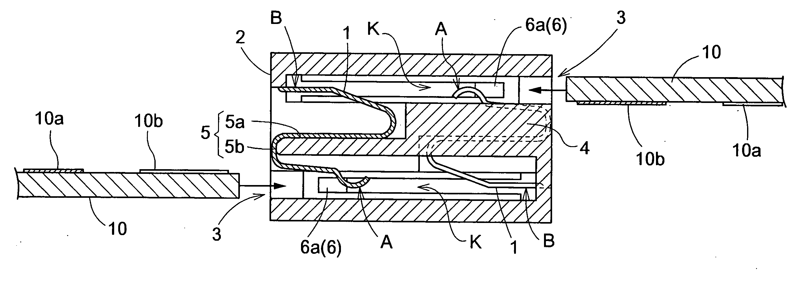
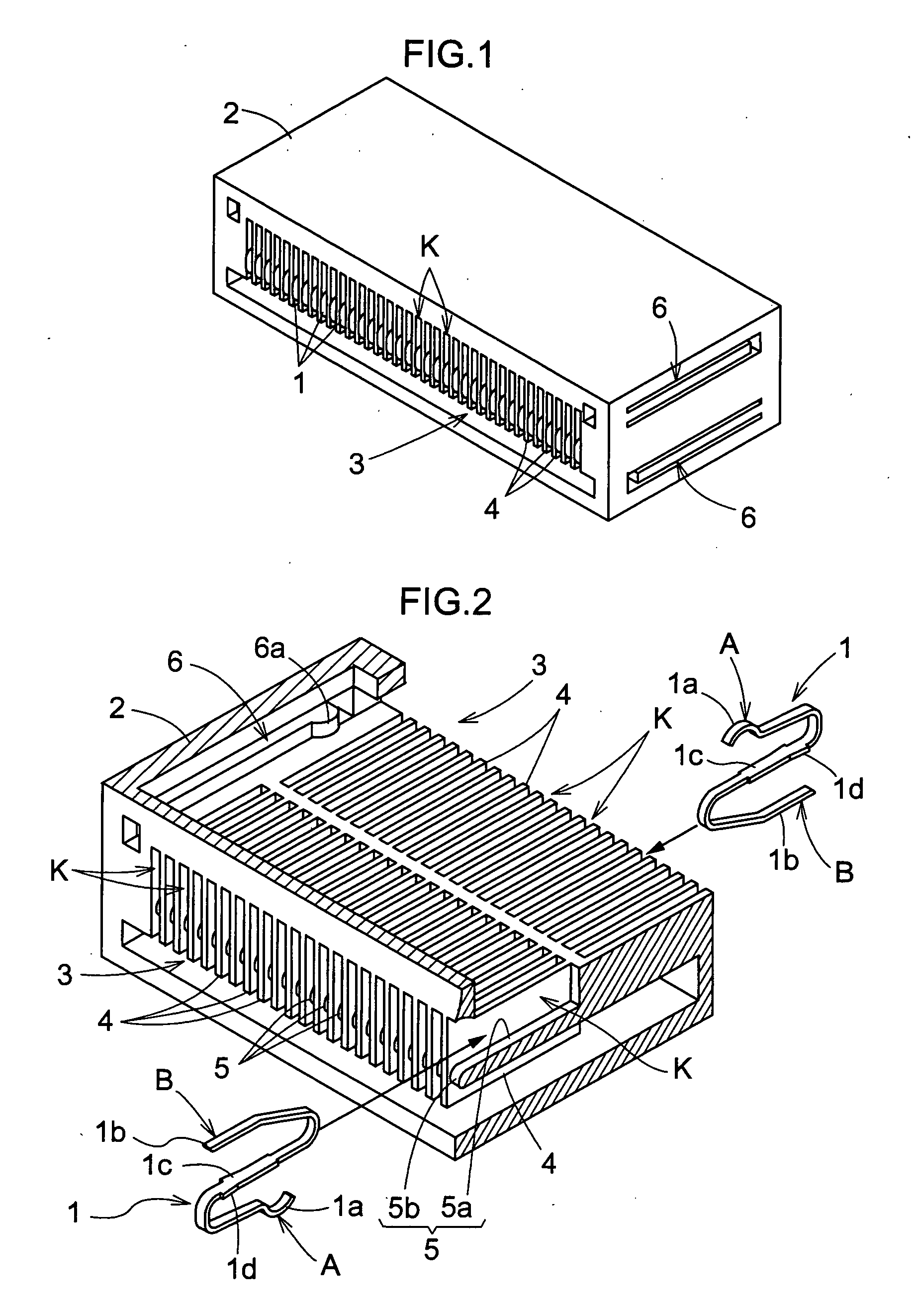
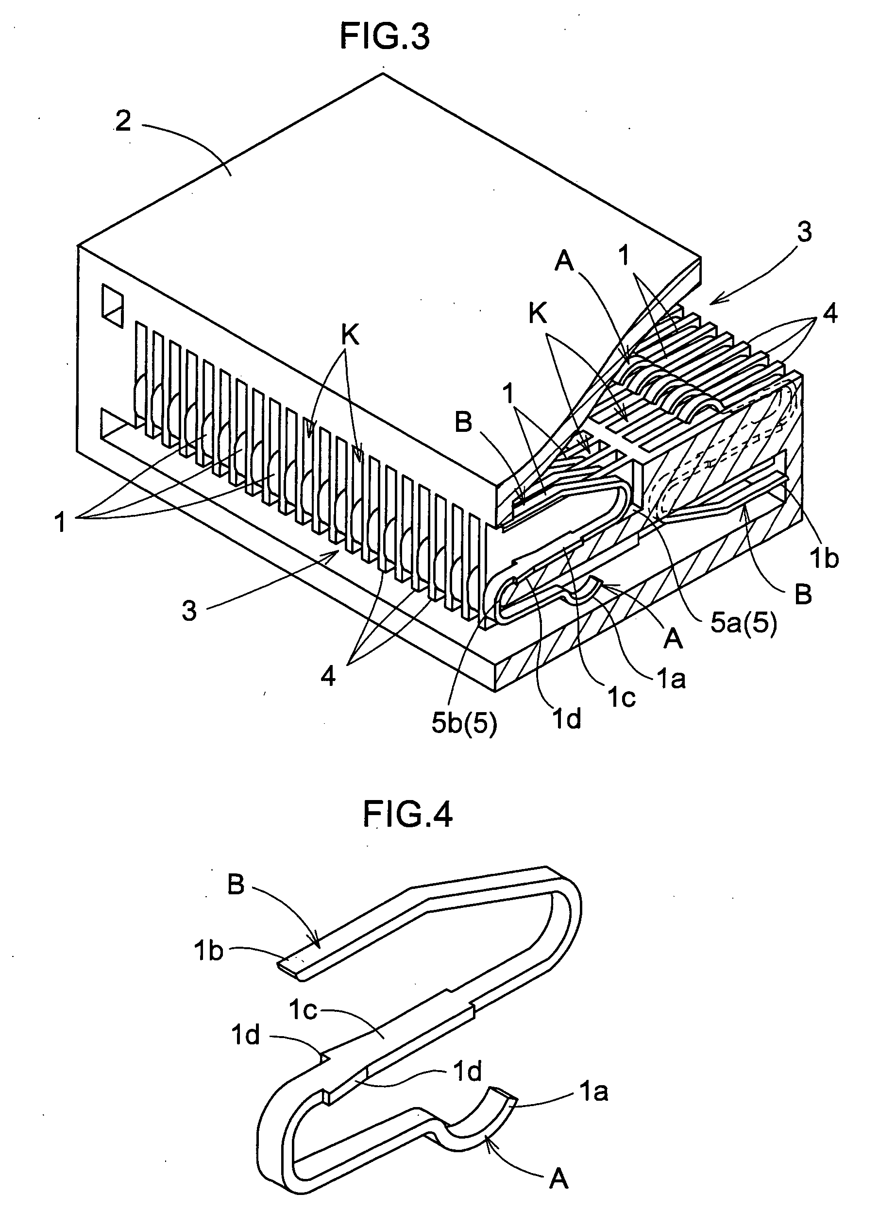
[0049] As shown in FIGS. 1 through 6, the connector according to this invention includes contact members 1 having elastically deformable points of contact A and B formed in two locations, and a main connector body 2 for insulating and holding a plurality of contact members 1 arranged at intervals in a width direction with the two points of contact A and B of the respective contact members 1 being in the same positions as seen in the direction of arrangement. FIG. 5 (b) is a cross section taken on line X-X shown in FIG. 5 (a), FIG. 6 is a view in vertical section taken on line Y-Y shown in FIG. 5 (a).

[0050] The above main connector body 2 has a pair of socket portions 3 for receiving board ends 10 defining land electrodes 10a and 10b corresponding to the poi...


PUM


Abstract

Disclosed are contact members which have elastically deformable points of contact formed in two locations, and a main connector body for insulating and holding a plurality of contact members arranged at intervals in a width direction with the points of contact in the two locations of the respective contact members being in the same positions as seen in the direction of arrangement. The main connector body includes a pair of socket portions for receiving board ends defining land electrodes in two rows corresponding to the points of contact of the respective contact members lying in the same positions as seen in the direction of arrangement, so that the land electrodes are in pressure contact with the corresponding points of contact.

Description

TECHNICAL FIELD [0001] The present invention relates to a connector for connecting printed circuit boards, flexible printed wiring boards (hereinafter abbreviated to FPC), or a printed circuit board and an FPC, for example. BACKGROUND ART [0002] As shown in FIG. 10, the above connector is used, for example, in a bending part (hinged part) of a folding type cell phone for connecting printed circuit boards in an upper case and a lower case. Specifically, in Example 1 in FIG. 10 (b), male connectors attached to the opposite ends of an FPC are inserted in female connectors with terminals thereof soldered to ends of the circuit boards in the respective cases (see Japanese Patent Publication “Kokai” No. 9-82439 (pages 4-6, FIGS. 1-14), for example). In Example 2 in FIG. 10 (c), electrodes formed at opposite ends of an FPC are inserted in female connectors with terminals thereof soldered to ends of the circuit boards in the respective cases (see Japanese Patent Publication “Kokai” No. 8-18...

Claims


Application Information

Patent Timeline
IPC IPC(8): H01R12/61H01R12/71H01R12/72H01R12/78H01R12/79H01R13/24H01R31/06H01R35/04
CPCH01R13/2435H01R12/721H01R12/79H01R12/714H01R12/58
Inventor NAGATA, TAKAYUKI
Owner HOSIDEN CORP
Why Eureka
Try Eureka