Gaming machine

a technology of a game machine and a display screen, applied in the field of games, can solve the problems of difficult to see symbols and images on the light transmittable area

Inactive Publication Date: 2005-12-22
UNIVERSAL ENTERTAINMENT CORP
View PDF25 Cites 45 Cited by
  • Summary
  • Abstract
  • Description
  • Claims
  • Application Information

AI Technical Summary

Benefits of technology

[0010] In order to dissolve the above problems, the present invention has been done and has an object to provide a gaming machine having a variable display device for conducting variable display of symbols and an image display device arranged in front of the variable display device, in which the symbol on the variable display device and the image displayed on the image display device can be easily seen.

Problems solved by technology

However, when light is irradiated on the rotation reel from the inner side thereof by utilizing the back light, the symbol irradiated by the back light and the image of the front display device are superimposed and displayed on the light transmittable area, therefore there is a problem that the symbol and the image on the light transmittable area are hard to be seen.

Method used


Image

  • Gaming machine
  • Gaming machine
  • Gaming machine

Examples


first embodiment

[0035] (Whole Construction Of The Slot Machine)

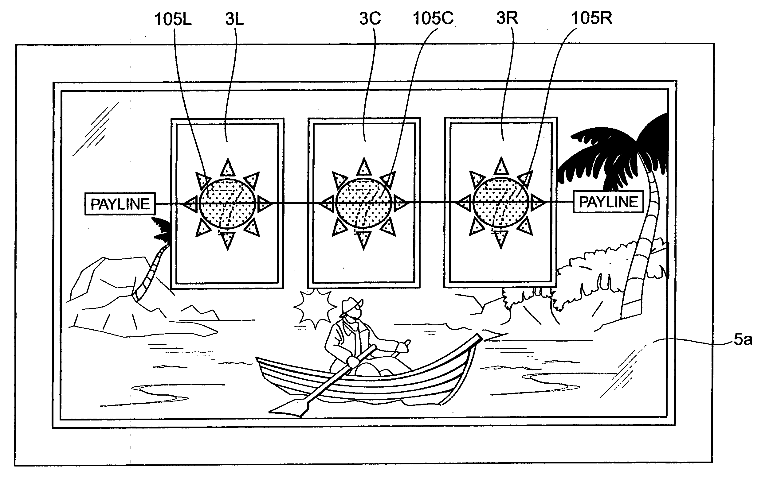
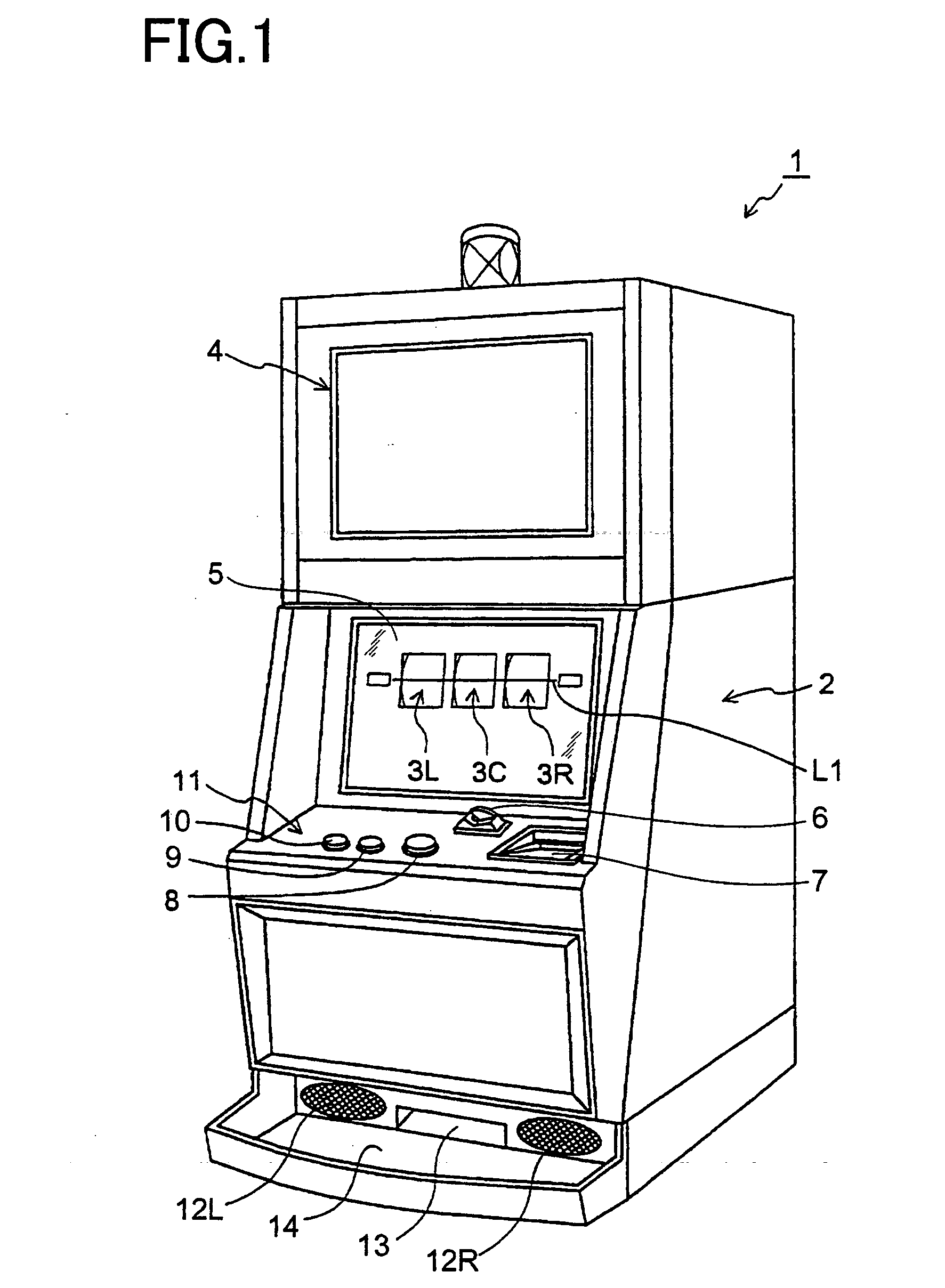
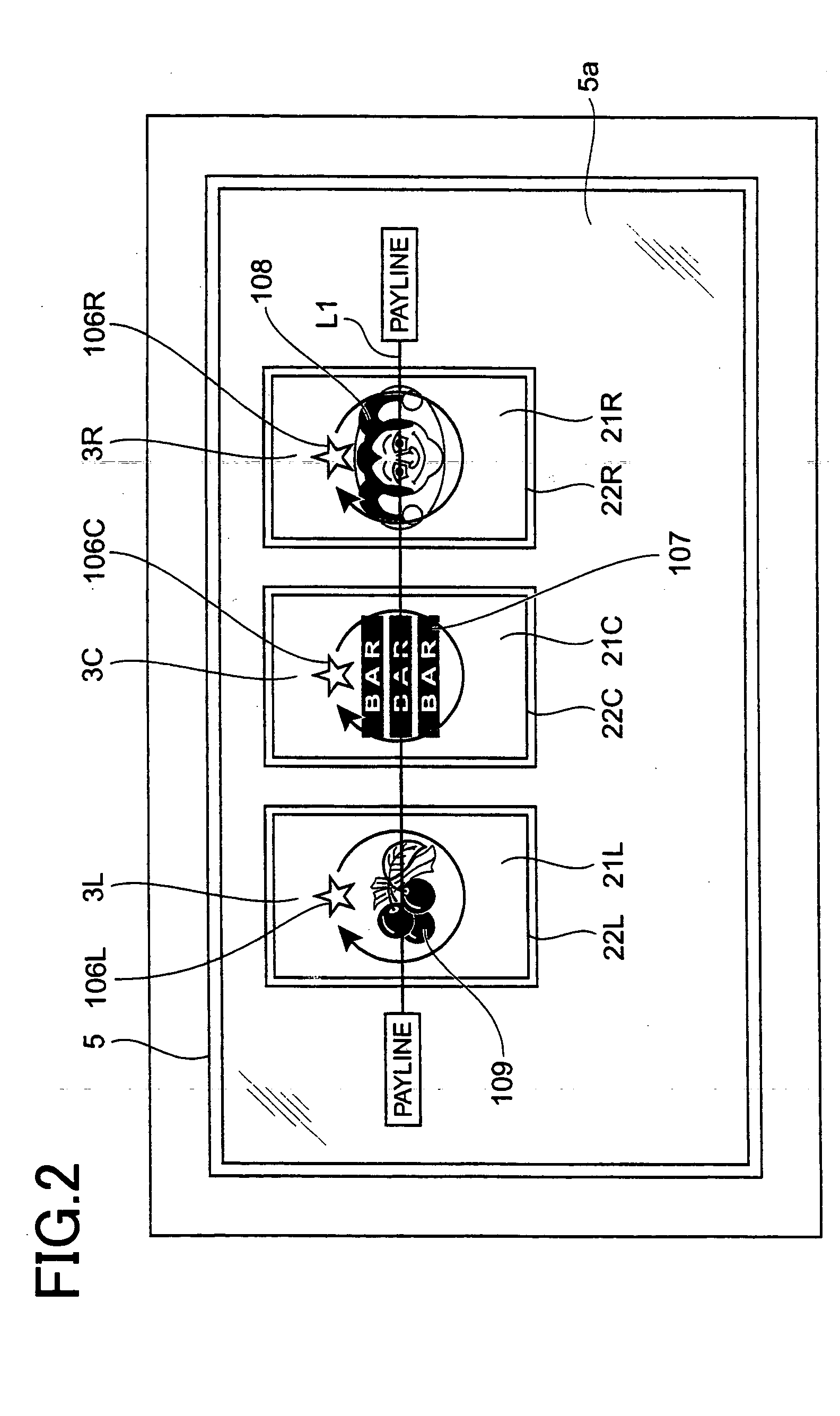
[0036]FIG. 1 is a perspective view showing whole construction of the slot machine 1. The slot machine 1 corresponding to the embodiment of the present invention has a variable display device for variably displaying symbols thereon and an image display device arranged in front of the variable display device. In the slot machine 1, it can be done a slot game by utilizing a plurality of symbols displayed on the variable display device.

[0037] The slot machine 1 has, according to an order from an upper position, an upper image display portion 4 arranged on a front plane of a cabinet 2 and a lower image display portion 5. The lower image display portion 5 is arranged in a center position of the cabinet 2 in a direction of the upper and lower positions and three mechanical reels 3L, 3C, 3R are rotatably arranged in the cabinet 2 along the horizontal line, so as to correspond to the lower image display portion 5.

[0038] Each of the reels 3L, ...

second embodiment

[0097] Next, the slot machine 1 according to the second embodiment will described. Comparing with the slot machine 1 of the first embodiment, the slot machine 1 of the second embodiment has different points from the slot machine 1 of the first embodiment at the following two points. That is, the first point is that a mirror plane process portion 201, on which a mirror plane reflection process is done, is formed on the outer periphery on each of the reels 3L, 3C, 3R as shown in FIG. 13. And the second point is that illumination control of both the LED lamps and the cold cathode ray tubes is conducted by the CPU 32. On the mirror plane process portion 201, for example, a mercury membrane is formed, thus light irradiated on the outer periphery of each reel 3L, 3C, 3R is reflected like a mirror.

[0098] As mentioned, since each of the reels 3L, 3C, 3R has the mirror plane process portion 201 on the outer periphery thereof, light irradiated from the cold cathode ray tubes 48a, 48b is refl...


PUM


Abstract

In the slot machine 1, there are provided a variable display device having a rotation member on an outer periphery of which a plurality of symbols are formed and the LED lamps arranged within the rotation member, a liquid crystal display device arranged in front of the variable display device, the liquid crystal display device having a light transmittable area through which light passes from a rear side thereof, wherein illumination control of the LED lamps is conducted so as to turn on the LED lamps when the display image on the light transmittable area is able to be displayed without superimposition with the display symbol and so as not to turn on the LED lamps when the display image on the light transmittable area is not able to be displayed without superimposition with the display symbol.

Description

CROSS-REFERENCE TO THE RELATED APPLICATION (S) [0001] This application is based upon and claims a priority from the prior Japanese Patent Application No. 2004-167697 filed on Jun. 4, 2004, the entire contents of which are incorporated herein by reference. BACKGROUND OF THE INVENTION [0002] 1. Field of the Invention [0003] The present invention relates to a gaming machine with an image display device arranged in front of a variable display device on which symbols are variably displayed. [0004] 2. Description of Related Art [0005] Conventionally, it is known a gaming machine in which a display device (front display device) is independently provided at a front side of a variable display device on which symbols are variably displayed. For example, as shown in Unexamined Japanese Publication No. 2001-252394, it is disclosed a gaming machine in which it is provided a rotation reel display device for conducting variable display of symbols and a light transmittable liquid crystal display de...

Claims


Application Information

Patent Timeline
Patent Type & Authority Applications(United States)
IPC IPC(8): A63F5/04G07F17/32G07F17/34
CPCG07F17/3211
Inventor TANIMURA, TATSUHIKOSEKIGUCHI, HIROFUMI
Owner UNIVERSAL ENTERTAINMENT CORP
Why Eureka
Try Eureka