
Back therapy device

a technology for back pain and therapy devices, applied in physical therapy, chiropractic devices, medical science, etc., can solve the problems of back injuries, work-related disability, staggering loss to the american society, etc., and achieve the effect of increasing comfort and increasing comfor

Inactive Publication Date: 2005-12-22
KAYE LAWRENCE +1
View PDF13 Cites 9 Cited by
  • Summary
  • Abstract
  • Description
  • Claims
  • Application Information

AI Technical Summary

Benefits of technology

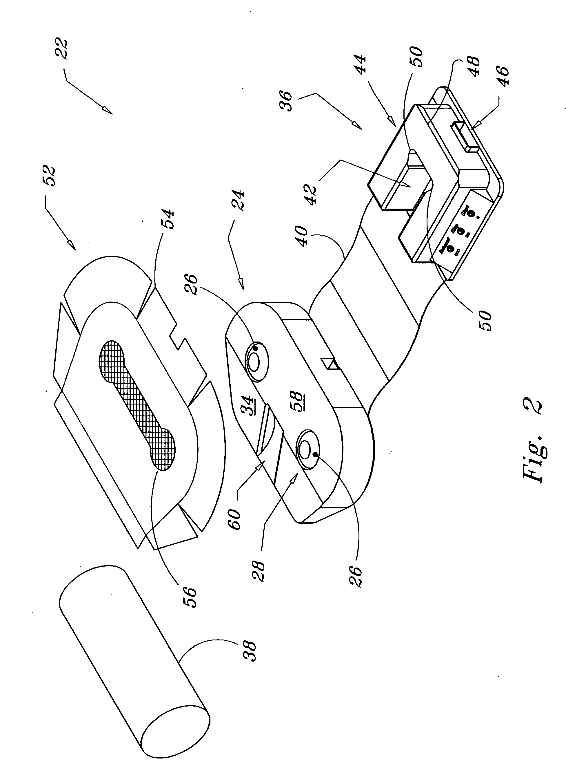
[0006] The face pad may be comprised of a substantially U-shaped face pad with an open center section and an upper connecting section. The open center section may include an expanded top portion, adjacent to the connecting section, whereby when a user's face is positioned thereon, the expanded top portion provides room lateral to the eyes of the user for increased comfort. Another addition to increase comfort includes providing a void near the base of the connecting section, thereby providing an air breathing passage for the user.
[0007] The system my also include a substantially flat chest mat connected to the pelvis pad and to the face pad. A pliable substantially cylindrical shin pad may also be added. The shin pad provides support for the lower legs of a user in a prone position when the midsection of the user is positioned on the pelvis pad.

Problems solved by technology

The same source notes that back injuries are the leading cause of work-related disability.
When lost wages and work time are also considered, the loss to the American society is staggering.
This may increase the displacement of the disk bulge toward the nerve cord, exacerbating the problem.

Method used


Image

  • Back therapy device
  • Back therapy device
  • Back therapy device

Examples


Embodiment Construction

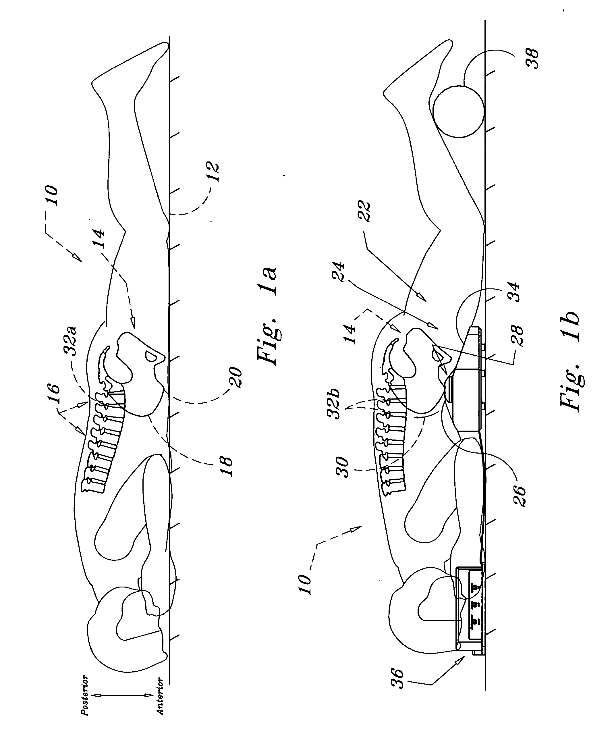
[0021] The present invention is a back therapy device. The general function of the device is shown in FIGS. 1a and 1b. In FIG. 1a, a person 10 is shown lying in a face down in a prone position on a flat surface 12. The pelvis 14 of the person 10 is illustrated in its natural position with the lumbar spine 16 including its natural curve or lordosis. The front sweeping portion of the pelvis is the illiac crest 18. Toward the anterior (in this view the lower) portion a bony protrusion exists. This protrusion is the anterior, superior illiac spine 20. The pelvis is supported by the long bones of the upper legs or the femur (not shown).

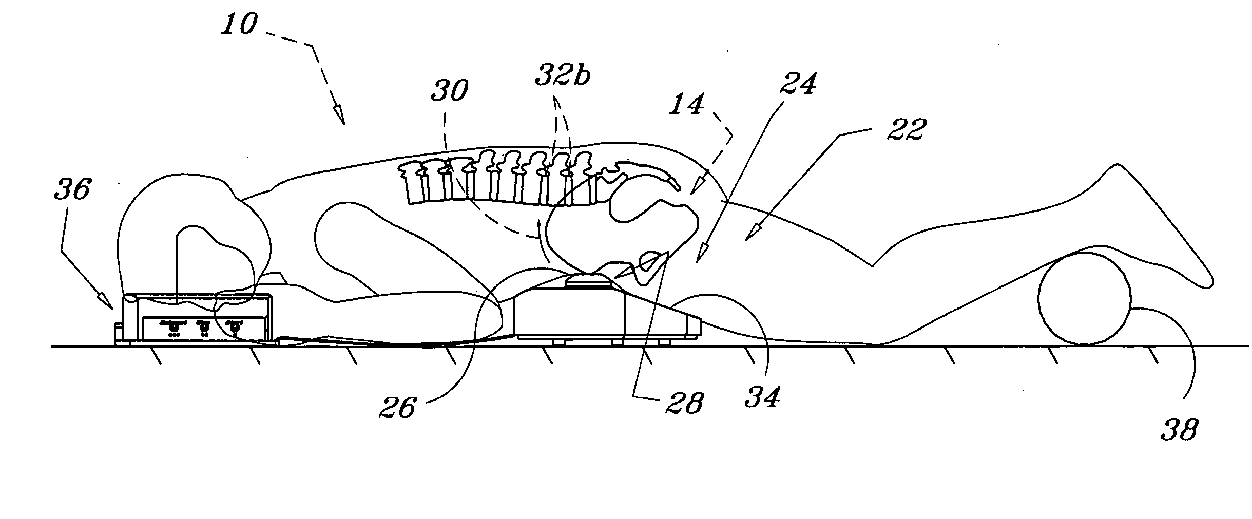
[0022] The same body is shown while using the device 22 in FIG. 1b. The invention may include some peripheral components, as will be disclosed in detail, but the primary component is the pelvis pad 24. This is positioned under the pelvis 14 of the user 10 with an upper portion 26 of a bladder 28 positioned under the illiac crest of the user. Optimally the...


PUM


Abstract

An inflatable bladder is used to articulate the spine of a user. A pelvis pad includes a support frame and a pliable cushion positioned thereon. The bladder is supported on the support frame and received by a void in the cushion. In the preferred embodiment the bladder includes two upper portions that extend away from the support frame toward the body of the user. The upper portions of the bladder, or two separate bladders, are cylindrical in shape when expanded. The void in the cushion is also cylindrical in shape and therefore acts to guide the expansion and contraction of the bladders or upper portions of the bladder. The upper portions are preferably positioned eleven inches apart and inflate at least two inches above the support frame. This proximity of the upper portions of the bladder fit the width of the right and left anterior superior illiac spine along the illiac crest of the pelvis. Expansion of the bladder applies a posterior force to the pelvis through the illiac crest and rotates the pelvis. This manipulates the lumbar spine to stretch the muscles of the lower back and increase the posterior disk spacing of the lumbar vertebrae, providing mild lumbar traction.

Description

FIELD OF THE INVENTION [0001] The present invention generally relates to therapy devices. More specifically, the present invention relates to devices for relief of acute lower back pain. BACKGROUND OF THE INVENTION [0002] Low back pain is the fifth-leading cause of trips to the doctor in the United States, according to the Mayo Clinic (Mayo Clinic Health Information, Jun. 3, 2004). The same source notes that back injuries are the leading cause of work-related disability. The National Institute of Neurological Disorders and Stroke reports that Americans spend at least $50 billion each year on low back pain. It is also estimated that approximately 80% of all Americans will encounter a bout with low back pain at some time in their lives (Mayo Clinic, 2004). When lost wages and work time are also considered, the loss to the American society is staggering. [0003] Traction devices have been used for many years with some success. The concept is to apply a tension load to the spine. In theo...

Claims


Application Information

Patent Timeline
Patent Type & Authority Applications(United States)
IPC IPC(8): A61F5/00A61F5/01A61H1/02A61H23/04
CPCA61F5/01A61F5/012A61H1/0218A61H2203/0468A61H9/0078A61H2201/163A61H1/0222
Inventor ABELBECK, KEVIN G.
Owner KAYE LAWRENCE
Learn More