
Intramedullary osteosynthesis implant

a technology of osteosynthesis and implants, applied in the direction of staples, nails, applications, etc., can solve the problems of pain, ulceration, infection, and considerable inconvenience for patients, and achieve the effect of stabilizing osteosynthesis and regulating the inclination or flexum

Inactive Publication Date: 2005-12-22
AMADEX
View PDF4 Cites 117 Cited by
  • Summary
  • Abstract
  • Description
  • Claims
  • Application Information

AI Technical Summary

Benefits of technology

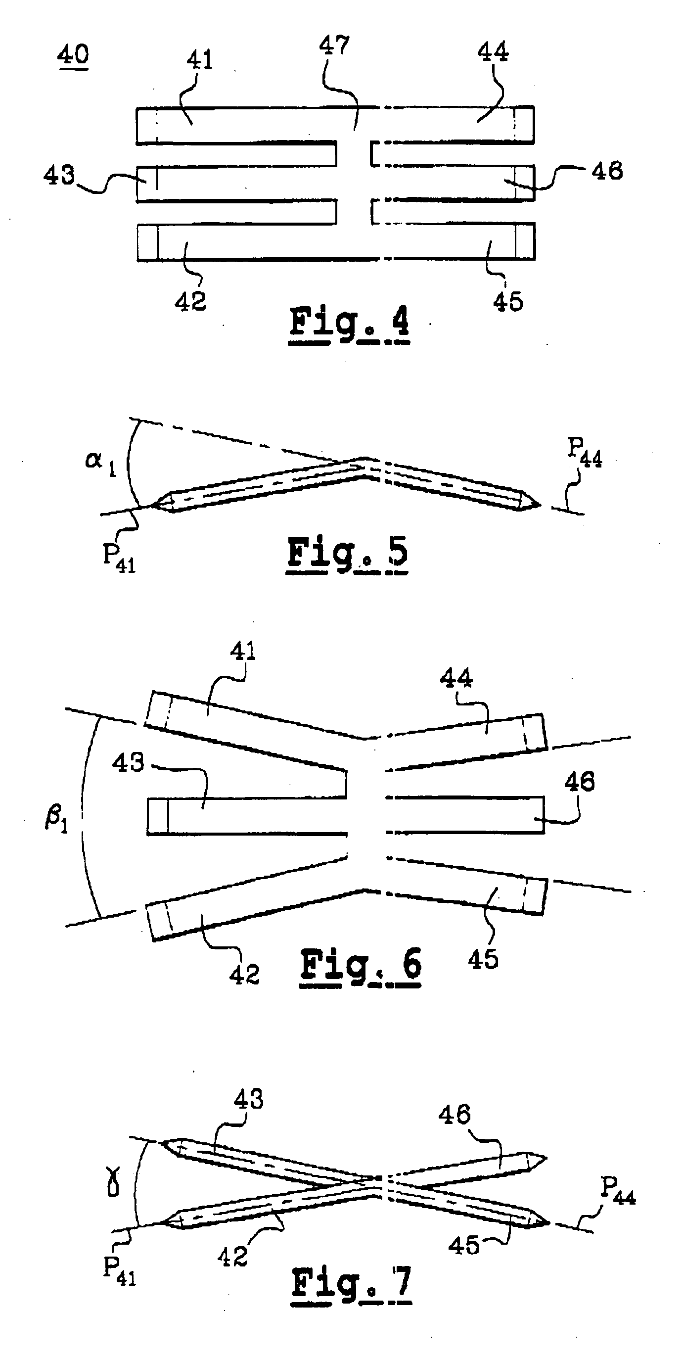
[0020] In accordance with the invention, this implant comprises two sets of at least two rods, and in practice two sets of two or three rods, without however excluding a possibly greater number of rods per set. Within the same set, these rods are substantially in the same plane and parallel to one another at ambient temperature. Each set of rods extends on either side of a central zone. Each set of rods is intended to be impacted in the diaphyseal medullary canal. Said central zone is in the form of a transverse rod or branch (horizontal) which, when cold, is perpendicular to the rods to be impacted. This central zone ensures the rigidity in flexion and substantial anti-rotation stability of the set, while maintaining a capacity for being angled, by virtue of its rectangular cross section. The implant is made from a shape-memory material so that, at body temperature, the rods of the same set spread apart in such a way as to be able to immobilize themselves in the medullary canal.
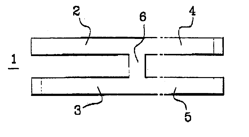
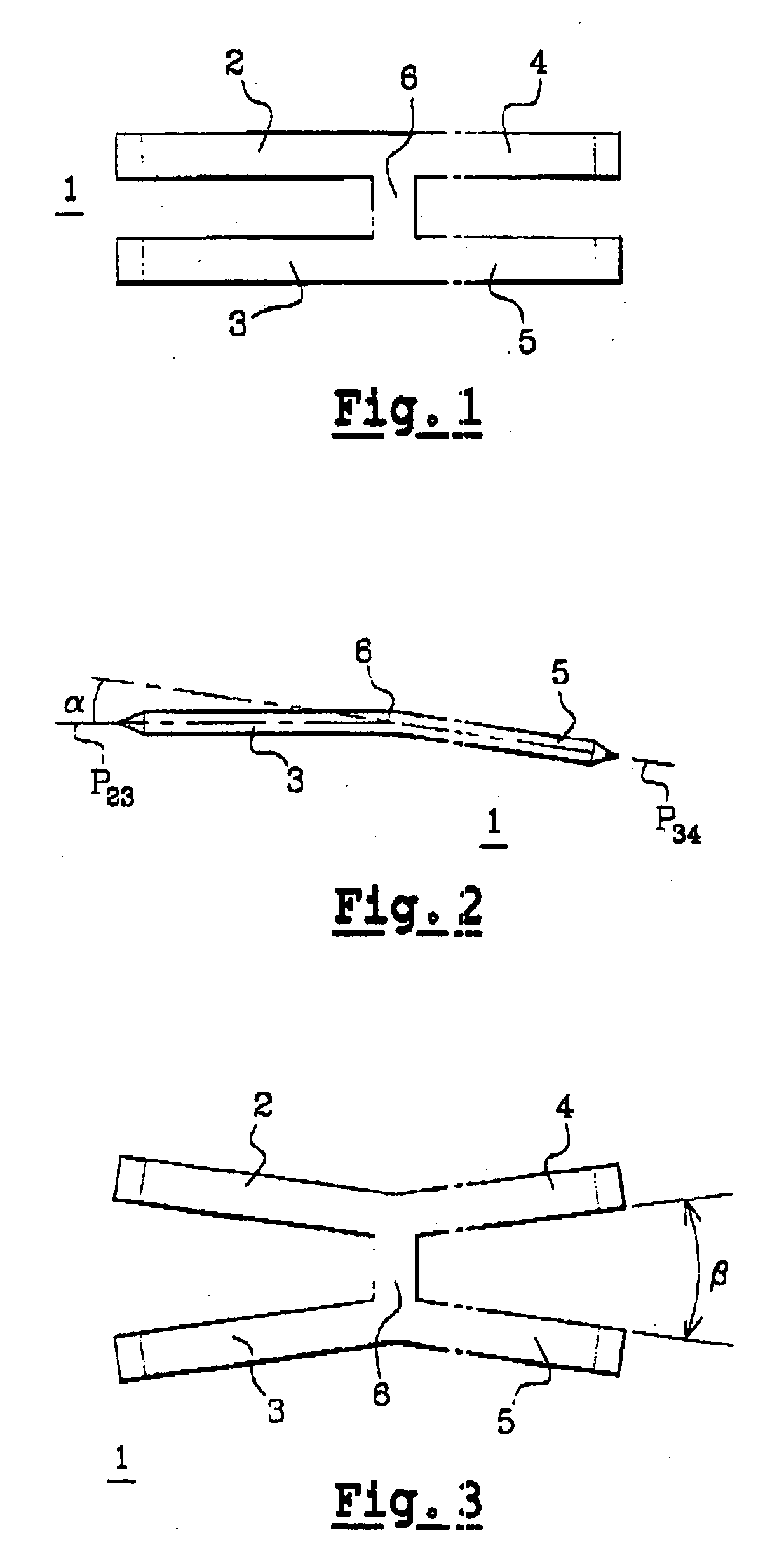
[0021] In other words, in the version with two pairs of rods, the implant comprises four rods connected in pairs to form a general H-shaped configuration which, when the temperature rises, deforms to adopt a general X-shape. When the implant is at ambient temperature, the rods of the same pair are parallel, thus permitting easy fitting in holes made for this purpose in the articular metaphysis. When the implant is exposed to a higher temperature, and in particular body temperature, the rods spread apart and anchor the implant in the diaphysis.
[0024] In practice, at ambient temperature, the planes defined by each set of rods advantageously form between them an angle of between 0° and 60°, making it possible to regulate the inclination or flexum of arthrodesis, that is to say the angulation between the bone structures (joints, diaphyses) once they are immobilized with respect to one another.
[0041] drilling holes to receive the rods (two or three depending on the implant model) in the medullary canal on the proximal bone then on the distal bone with the aid of a suitable ancillary or with the aid of drill bits and an osteosynthesis motor. In the case of drilling several holes with the aid of drill bits, their spacing is ensured by virtue of a drill guide with apertures spaced apart by the desired distance between the holes. A guide pin introduced into one of the already drilled holes makes it possible to keep the drill guide correctly positioned.
[0044] A so-called “phantom” implant makes it possible to simulate the arthrodesis or diaphyseal osteosynthesis before fitting the shape-memory implant. This “phantom” makes it possible to correct any error in position of the implant, and in particular the errors of angulation in the frontal, sagittal and horizontal planes.

Problems solved by technology

In practice, this arthritis is manifested by pain particularly when the patient makes a gripping movement between the thumb and index or middle finger, which are the fingers most subjected to stress.
These deformations cause difficulties in gripping or result in instabilities of the joint which cause problems if executing movements requiring a certain precision or adequate force.
These different osteosynthesis fixtures cause considerable inconvenience for the patient.
In addition, the pins present under the pulp can cause pain, ulceration, or infection, even perforation of the skin.
In any event, they cause considerable functional impairment in most cases because the patient no longer uses his finger for quite a long period of time.
In addition, in about 20% of cases, this arthrodesis causes major complications, among which osteitis, deep infection, or malposition of the two phalanges after osseous fusion.

Method used


Image

  • Intramedullary osteosynthesis implant
  • Intramedullary osteosynthesis implant
  • Intramedullary osteosynthesis implant

Examples


Embodiment Construction

[0055] The arthrodesis implant (1) illustrated in FIG. 1 comprises two pairs of rods (2, 3, 4, 5) which are substantially parallel and are connected to a central portion (6) in such a way that the implant (1) has a general H-shape.

[0056] The implant illustrated in FIG. 1 is used especially for arthrodesis of the distal interphalangeal joint of the hands and the proximal interphalangeal joints of the toes. This implant has a total length of the order of 14 millimeters.

[0057] The total width of the implant (1), in the configuration at ambient temperature illustrated in FIG. 1, is of the order of 4.5 millimeters. Each rod has a width of the order of 1.1 millimeter. The rods of the same pair are separated by a space of the order of 4.5 millimeters.

[0058] In the form illustrated, the rods (2, 3) intended to be impacted in the joint or the proximal diaphysis are slightly longer than the rods (4, 5) intended to be impacted in the joint or the distal diaphysis. More precisely, in the exa...


PUM


Abstract

Intramedullary osteosynthesis implant, permitting in particular arthrodesis (1) of a joint, for example an interphalangeal joint, or diaphyseal osteosynthesis of the upper limb or of the lower limb, comprising two sets of at least two rods (2, 3, 4, 5) each extending on either side of a central zone (6), said rods (2, 3; 4, 5) being substantially parallel at ambient temperature within the same set, each set of rods being intended to be impacted in the medullary canal of a diaphysis, said implant being made from a shape-memory material so that, at body temperature, the rods (2, 3; 4, 5) of the same set spread apart so as to be able to immobilize themselves in said medullary canal.

Description

TECHNICAL FIELD [0001] The invention concerns the field of surgical treatment of articular lesions with arthritis and / or deformation of the joints of the upper limb and of the lower limb, the therapeutic objective being to immobilize the joint by osseous fusion. [0002] It concerns more particularly an arthrodesis implant and a surgical method of treating degenerative or post-traumatic arthritis and articular deformations by fitting such an implant. [0003] The implant is also used as a means of intramedullary osteosynthesis when osseous fusion is sought in trauma surgery or corrective surgery. [0004] In this application, the object is to obtain fusion and osseous consolidation of a diaphyseal or articular bone by means of an intramedullary implant. PRIOR ART [0005] Arthritis of the interphalangeal joints, whether of the foot or of the hand, is generally quite common, considering that it affects about 20% of the population over 55 years of age and 40% over 70 years of age. [0006] In p...

Claims


Application Information

Patent Timeline
IPC IPC(8): A61B17/00A61B17/72A61B17/86
CPCA61B17/7266A61B2017/00867A61B17/7291
Inventor AMARA, BOUALI
Owner AMADEX
Learn More