Method and apparatus for ion source positioning and adjustment

a technology of ion source and positioning device, which is applied in the field of cyclotron design for radiopharmacy, can solve the problems of difficult to achieve the optimal position of the ion source tube, the traditional approach to ion source positioning and adjustment can be very time-consuming, and the output of the ion source does not offer a clear indication

Active Publication Date: 2005-12-22
GENERAL ELECTRIC CO
View PDF9 Cites 49 Cited by
  • Summary
  • Abstract
  • Description
  • Claims
  • Application Information

AI Technical Summary

Problems solved by technology

Unfortunately, a simple reading of the ion source output does not offer a clear indication as to which direction or by how much the ion source tube should be adjusted.
Therefore, the traditional approach for ion source positioning and adjustment can be very time-consuming.
Even when an acceptable level of ion source output has been achieved, it is seldom clear whether an optimal position of the ion source tube has been reached.
Unfortunately, ion source adjustment is hardly avoidable since an ion source typically has a limited lifetime and requires periodical replacement.
However, since the cyclotron usually becomes radioactive during isotope production, it is necessary to wait for the radiation to decay to a safe level before starting the service.
Therefore, the shorter it takes to position and adjust a new ion source, the faster a scheduled service may be completed.

Method used


Image

  • Method and apparatus for ion source positioning and adjustment
  • Method and apparatus for ion source positioning and adjustment
  • Method and apparatus for ion source positioning and adjustment

Examples


Embodiment Construction

[0020] Reference will now be made in detail to exemplary embodiments of the invention, examples of which are illustrated in the accompanying drawings.

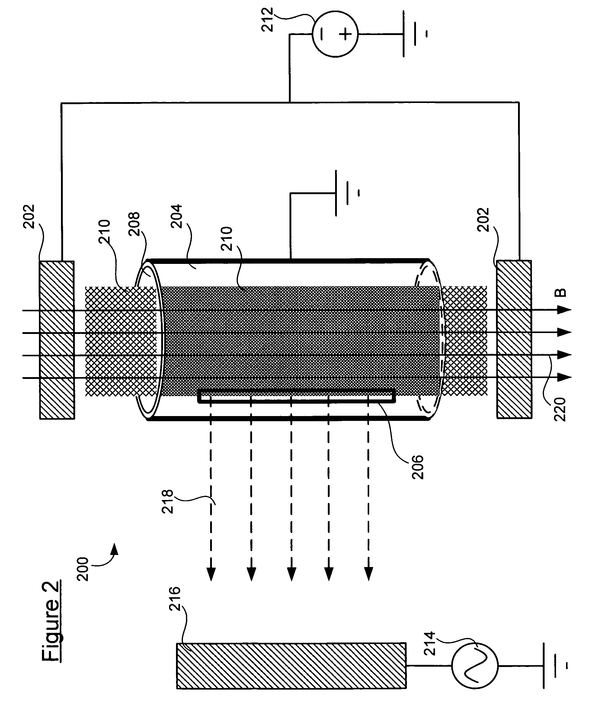
[0021] In an ion source similar to the one shown in FIG. 2, positioning of the slit opening relative to the puller is a significant factor affecting ion extraction. The position of the ion source tube usually has to be accurate within a fraction of a millimeter. Accurate positioning of the ion source tube usually depends on three parameters: its distance to the puller (or “longitudinal position”), the lateral position of the slit opening relative to the puller, and angle of the slit opening with respect to the ion source body. Of these three parameters, the lateral position of the slit opening is usually most significant. The distance to the puller and the lateral position may be accurately and efficiently adjusted based on the method and apparatus described hereinafter. The angle of the slit opening may be fixed easily by a special a...


PUM


Abstract

The invention is directed to a method and apparatus for ion source positioning and adjustment. According to one embodiment, the invention relates to an apparatus for ion source positioning and adjustment. The apparatus comprises a bottom plate, a middle plate and a top plate, wherein the top plate is coupled to the middle plate by at least one adjustment member for causing the top plate to move in a first direction, wherein the at least one adjustment member positions the top plate in a predetermined position with respect to the middle plate; and the middle plate is coupled to the bottom plate by a worm gear assembly for causing the middle plate to move in a second direction with respect to the bottom plate.

Description

BACKGROUND OF THE INVENTION [0001] The present invention relates generally to the field of cyclotron design for radiopharmacy and more particularly to a method and apparatus for ion source positioning and adjustment. [0002] Hospitals and other health care providers rely extensively on positron emission tomography (PET) for diagnostic purposes. PET scanners can produce images which illustrate various biological process and functions. In a PET scan, the patient is initially injected with a radioactive substance known as a PET isotope (or radiopharmaceutical). The PET isotope may be 18F-fluoro-2-deoxyglucose (FDG), for example, a type of sugar which includes radioactive fluorine. The PET isotope becomes involved in certain bodily processes and functions, and its radioactive nature enables the PET scanner to produce an image which illuminates those functions and processes. For example, when FDG is injected, it may be metabolized by cancer cells, allowing the PET scanner to create an ima...

Claims


Application Information

Patent Timeline
Patent Type & Authority Applications(United States)
IPC IPC(8): A61N1/18G21G1/10G21G4/08H01J27/02H05H7/00H05H13/00H05H13/02
CPCH05H13/00H05H7/00
Inventor NORLING, JONAS OVEBERGSTROM, JAN-OLOF
Owner GENERAL ELECTRIC CO
Why Eureka
Try Eureka