Distributed generation modeling system and method

a distribution generation and modeling system technology, applied in the field of electric generator analysis, can solve the problems of fuel cost and projected maintenance cos

Inactive Publication Date: 2005-12-22
BASIC RESOURCES
View PDF23 Cites 34 Cited by
  • Summary
  • Abstract
  • Description
  • Claims
  • Application Information

AI Technical Summary

Benefits of technology

[0011] The present invention provides a profusion of technical advantages and other benefits that include one or more of the following. One such technical advantage of the present invention includes the capability to conveniently and easily determine an accurate assessment of the value of acquiring a generator or local generation to supplement or, in some instances, replace electricity provided through the grid.
[0012] An advantage of the present invention includes calculating a preliminary dispatch that may be obtained by determining, such as on an hourly basis, periods of time where the variable or incremental cost to generate electricity is less than the cost to purchase electricity from the grid for the customer. While yet another advantage of the present invention may include computing a dispatch, on an hourly basis, where the sum of the operating costs for operating the generator for the period combined with the actual generation costs including the fuel and start-up costs are less than the electricity costs to purchase electricity from the grid for the period.
[0013] Other technical advantages and benefits are readily apparent to one skilled in the art from the following

Problems solved by technology

This may further include fuel costs and projected maintenance costs.

Method used


Image

  • Distributed generation modeling system and method
  • Distributed generation modeling system and method
  • Distributed generation modeling system and method

Examples


Embodiment Construction

[0024] It should be understood at the outset that although an exemplary implementation of the present invention is illustrated below, the present invention may be implemented using any number of techniques, whether currently known or in existence. The present invention should in no way be limited to the exemplary implementations, drawings, and techniques illustrated below, including the exemplary design and implementation illustrated and described herein.

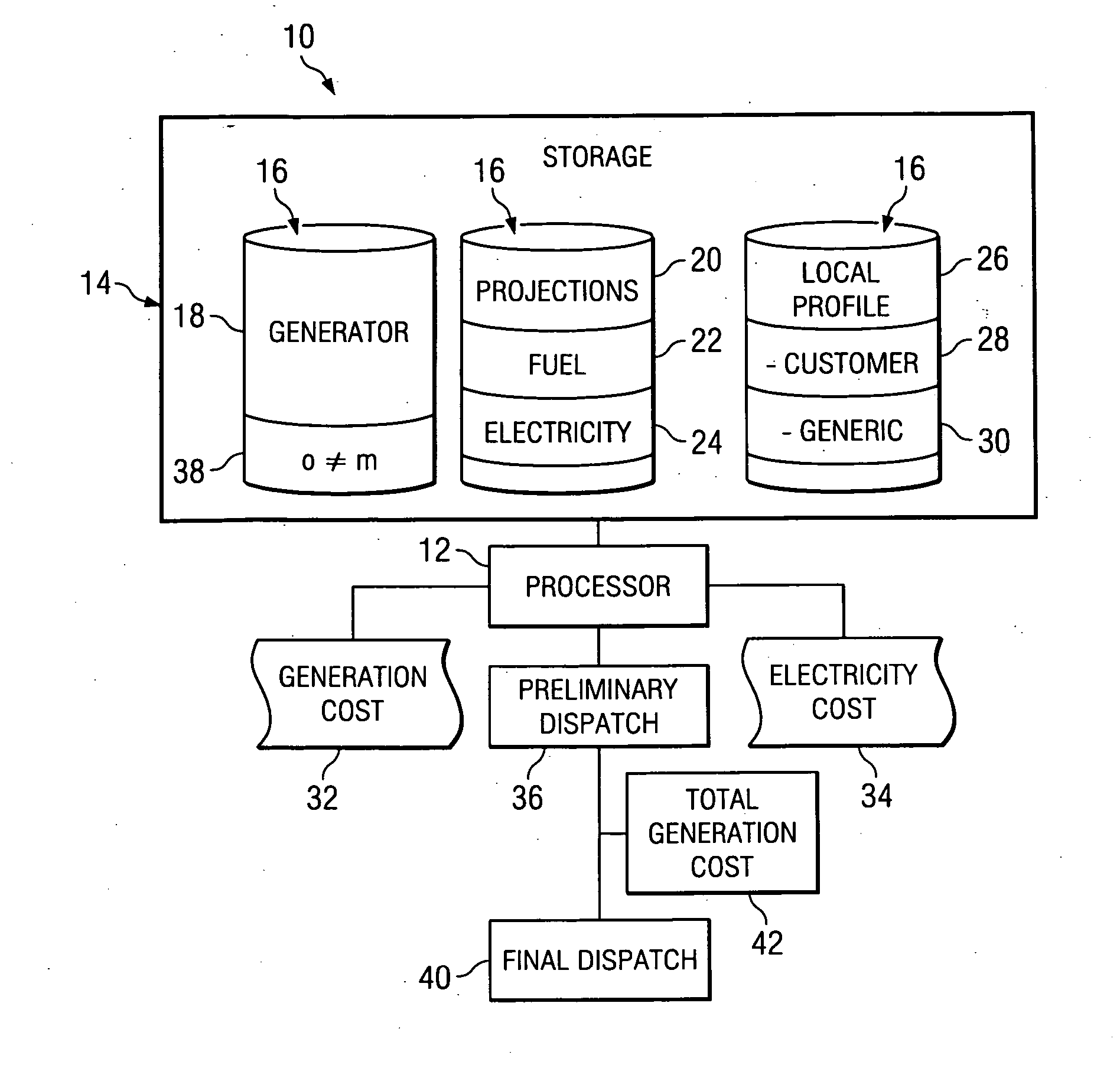
[0025]FIG. 1 illustrates one aspect of a distributed generation modeling system 10 of the present invention. The present invention is a unique system and method useful for analyzing the use of local or distributed electric generation, which may be distributed at the customer or other locations, to provide lower cost electricity at certain times. In one embodiment of the distributed generation modeling system 10, multiple generators may be modeled so that various generators may be compared to determine which generator may be the mos...


PUM


Abstract

An exemplary system for analyzing and modeling electric generators for a customer is provided. The system may include a database component and processor. The database operable to maintain data identifying a generator, a generator fuel cost projection, operating parameters, a customer load profile, and an electricity cost projection for a period of time. The processor operable to calculate a projected generation cost, and to compare the projected generation cost with the electricity cost projections to provide electricity to the customer through an electric grid. A method for modeling distributed generation is also provided. The method includes determining a projected customer electric cost to provide electricity to a customer from the electric grid and determining a projected generation cost for a generator to generate electricity for the customer for the period of time to meet the customer's projected load or electric load profile.

Description

TECHNICAL FIELD OF THE INVENTION [0001] This invention relates generally to the field of analyzing electric generators for use by a customer and more particularly, but not by way of limitation, to a distributed generation modeling system and method. BACKGROUND OF THE INVENTION [0002] Residential and commercial electric customers ordinarily obtain electricity from the electric grid of the local electric service provider. Unfortunately, power outages on the electric grid are not uncommon and may cause a significant disruption to the customer. For this reason, the customer may obtain an alternate source of electricity, such as local, backup or emergency generator, to provide electricity in the event of a power outage from the local electric service provider. [0003] Electric generators are available in a wide variety of models with varying levels of electric generation capacity, operational considerations and cost. The generator may be located at the customer's site and configured to pr...

Claims


Application Information

Patent Timeline
Patent Type & Authority Applications(United States)
IPC IPC(8): G01R11/63G01R19/165G01R19/30H02J3/00
CPCH02J3/00Y02E60/76Y04S40/22H02J2003/007H02J2203/20Y02E60/00Y04S40/20
Inventor ELKINS, HAROLD EDWARD IISANDERFORD, FREEMAN MURRAY II
Owner BASIC RESOURCES
Why Eureka
Try Eureka