
Manufacturing method of optical fiber and optical fiber

a manufacturing method and technology of optical fiber, applied in the field of manufacturing methods of optical fiber and optical fiber, can solve the problems of large difficult stable drawing of the drawn fiber, and breakage of the fiber, so as to achieve less fluctuation in the outer diameter of the drawn fiber. , the effect of less breakag

Inactive Publication Date: 2005-12-29
SUMITOMO ELECTRIC IND LTD +1
View PDF8 Cites 4 Cited by
  • Summary
  • Abstract
  • Description
  • Claims
  • Application Information

AI Technical Summary

Benefits of technology

[0006] It is therefore an object of the present invention to provide a manufacturing method of an optical fiber having a multi-component glass core with less fluctuation in its outer diameter and less breakage.

Problems solved by technology

However, with the method disclosed by the above-described document, when the core material made of multi-component glass (hereinafter, also referred to as a multi-component glass core), which has been disposed in a cladding tube made of silica glass, is heated and drawn, there may be cases that the fluctuation in the outer diameter of the drawn fiber becomes large, and this results in breakage of the fiber and its stable drawing becomes difficult.

Method used


Image

  • Manufacturing method of optical fiber and optical fiber
  • Manufacturing method of optical fiber and optical fiber

Examples


example 1

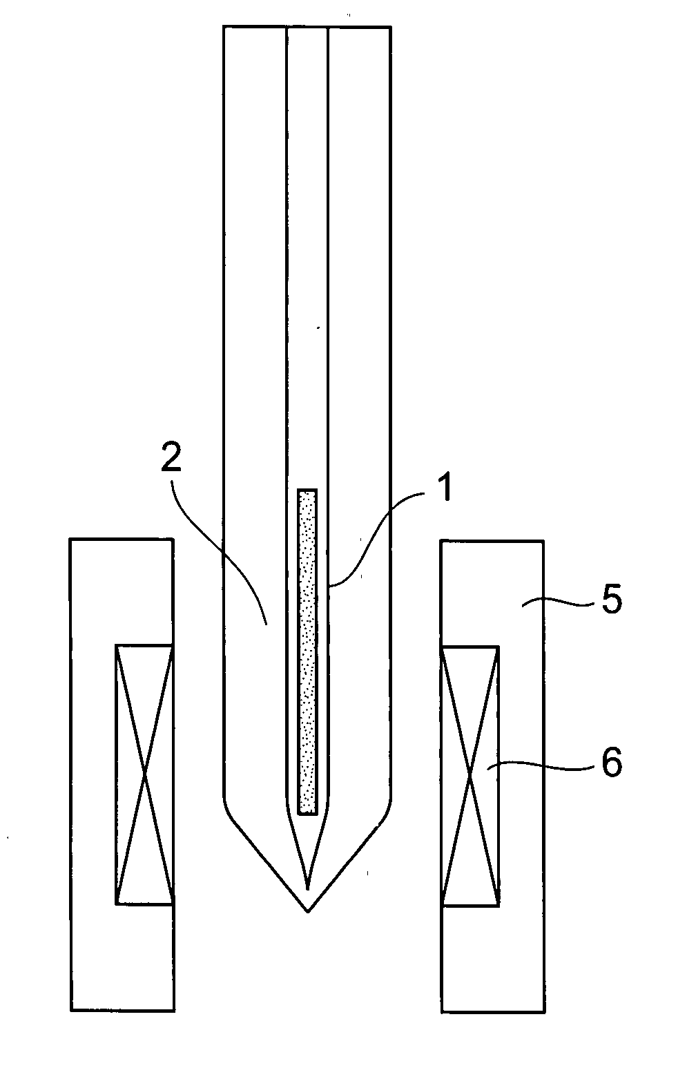
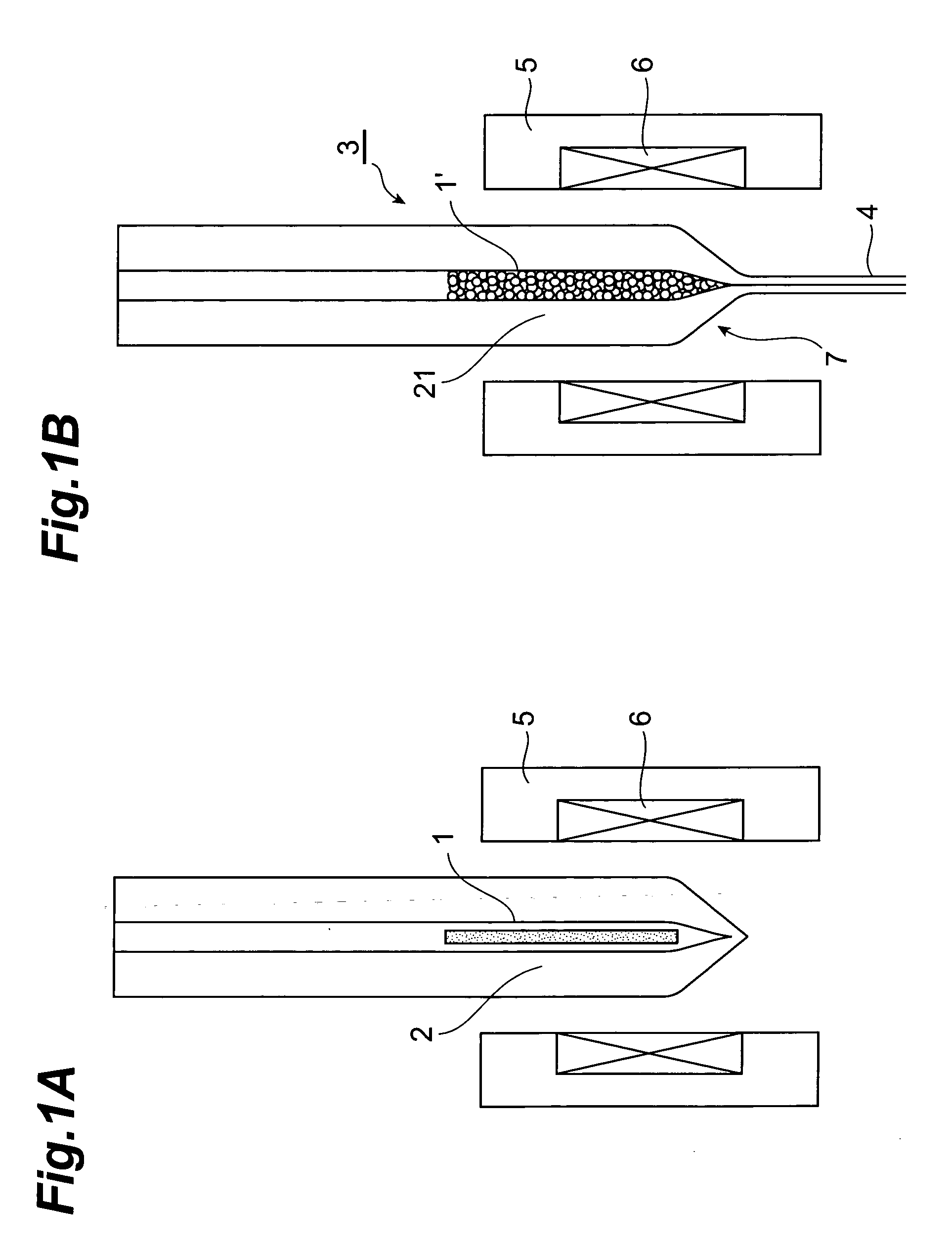
[0033] In the configuration shown in FIGS. 1A and 1B, as the core rod 1, the multi-component glass core rod; which is composed of 32 wt. % of Al2O3, 20 wt. % of Y2O3, 0.1 wt. % of Er2O3, and SiO2 being the remaining part; is prepared, and the cladding tube 2 made of SiO2 containing 3 wt. % of F (F is added homogeneously in the entire tube) is prepared. The core rod 1 is 6 mm Φ in outer diameter and 200 mm in length, and the cladding tube 2 is 40 mm in outer diameter, 8 mm in inner diameter, and 400 mm in length. The core rod 1 and the cladding tube 2, which have not been unified at a stage of a preform, are unified at the time of heating and drawing by the drawing furnace 5. When the drawing is applied to form the optical fiber 4 whose outer diameter is 125 μm under the conditions that the drawing tension is 0.1 to 0.8 N, the drawing tension at the steady state is 0.6 N, the drawing speed is 100 m / minute, and the drawing temperature is 1750° C. (furnace temperature), the fluctuation...


PUM

PropertyMeasurementUnit
Temperatureaaaaaaaaaa
Forceaaaaaaaaaa
Currentaaaaaaaaaa

Abstract

There is disclosed a method of manufacturing an optical fiber whose core is made of multi-component glass without fluctuation in its outer diameter and occurrence of sudden breakage thereof, with a technique of unifying a core rod and a cladding tube at the time of drawing, and yet drawing them; and the optical fiber having a multi-component glass core are disclosed.

Description

BACKGROUND OF THE INVENTION [0001] 1. Field of the Invention [0002] The present invention relates to a manufacturing method of an optical fiber having a multi-component glass core and the optical fiber. [0003] 2. Related Background of the Invention [0004] As one of the manufacturing methods of an optical fiber, the method; in which in a state where a softened core raw material is filled in a hollow part of the tube, which is obtained by disposing a solid core raw material in the hollow glass tube having a cladding structure and heating them, they are drawn as they stand; has been proposed. According to this method, the core raw material, which has been melted and adapted on the inside wall of the hollow part of the cladding tube, can be immediately fiberized in this state. Therefore, this method is considered to have the following advantages: (a) this method does not require a polishing process for smoothing the surface of the core rod, which a rod-in-tube method requires; and (b) w...

Claims


Application Information

Patent Timeline
IPC IPC(8): G02B6/00C03B37/012C03B37/027C03B37/075C03C13/04
CPCC03B37/02754C03B2201/10C03B2201/12C03B2201/28C03C13/046C03B2205/14C03B2205/40C03B2205/72C03B2201/36
Inventor TARU, TOSHIKIISHIKAWA, SHINJIHARUNA, TETSUYAKAKUI, MOTOKIMURATA, TAKAHIRO
Owner SUMITOMO ELECTRIC IND LTD
Learn More