Screwdriver fast connector

a screwdriver and connector technology, applied in the direction of screwdrivers, power-driven tools, wrenches, etc., can solve the problems of preventing easy control of precision, lack of consistent positioning of straight parts, and complicated screwdrivers, so as to improve the structure of screwdriver fast connectors and facilitate mounting , the effect of fast removal of the screwdriver tip

Inactive Publication Date: 2005-12-29
HUANG PING WEN
View PDF7 Cites 4 Cited by
  • Summary
  • Abstract
  • Description
  • Claims
  • Application Information

AI Technical Summary

Benefits of technology

[0007] The primary purpose of the present invention is to provide an improved structure of a screwdriver fast connector that allows easier mounting and faster removal of a tip of the screwdriver.
[0008] To achieve the purpose, a screwdriver fast connector of the present invention is comprised of a shank, a locking member and a slide member. An insertion channel is provided to the shank to receive the placement of the tip and an accommodation hole is connected through the bottom of the insertion channel and adapted with a coil. The coil under normal condition is partially protruding from the accommodation hole to generate the force needed to eject the bit. An accommodation channel is axially disposed to the outer edge of the shank and the distal end of the accommodation channel from the accommodation hole is disposed with an elastic member penetrating the shank in radius. The locking member includes a steel bead and an elastic member. The elastic member is installed in the accommodation channel; and the steel bead is installed in the accommodation channel at the approximate end towards the radius hole to protrude into the insertion channel as pushed against by the elastic member. The slide member includes a sleeve, an elastic member and a C-clamp. The sleeve is disposed to the outer edge of the shank and adapted with a recess and a C-shaped slot on the inner edge of the sleeve. The elastic member is placed in the recess and holds against a flange provided externally to the shank. The C-clamp inside the C-shaped slot locks up the distal end of the flange away from the elastic member to keep the sleeve from falling out of the shank. Under normal condition, a first accommodation space and a second accommodation spaces are provided to the sleeve in relation to where the steel bead is located. A retaining part is defined between the first and the second accommodation spaces to be held against by the steel bead at where in relation to the location of the steel bead. The other side of the second accommodation space in relation to the retaining part of the second accommodation space closer to the side of the accommodation hole is where the first accommodation space is located. Once the tip is inserted into the insertion channel, the steel bead as pushed by the tip slides into the second accommodation space. To remove the tip, the sleeve is moved for the steel bead to enter into the first accommodation space where the coil will push out the tip. Accordingly, the present invention provides a fast connector to easily mount and dismount the tip of a screwdriver.

Problems solved by technology

However, the process to provide the flute 71 is complicate and prevents easy control of precision resulting in the absence of a consistent positioning for the straight part 721.

Method used


Image

  • Screwdriver fast connector
  • Screwdriver fast connector
  • Screwdriver fast connector

Examples


Embodiment Construction

[0017] Referring to FIGS. 1 through 5 for a preferred embodiment selected for the description of the present invention, it is to be noted that the claims made hereunder are not restricted by the construction disclosed in the preferred embodiment.

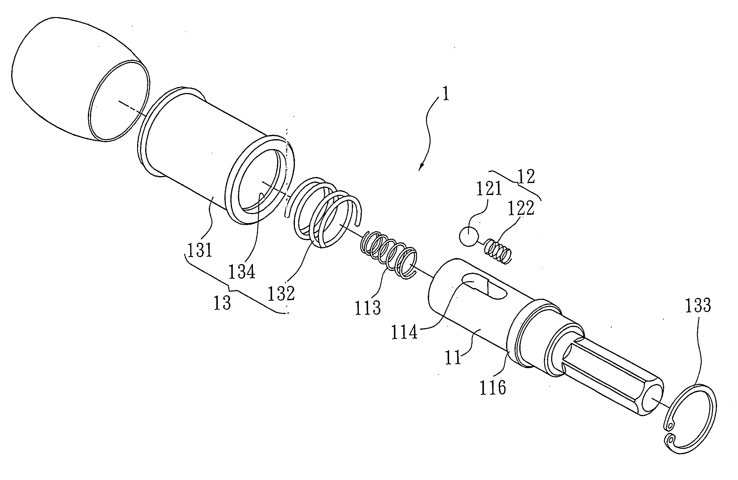
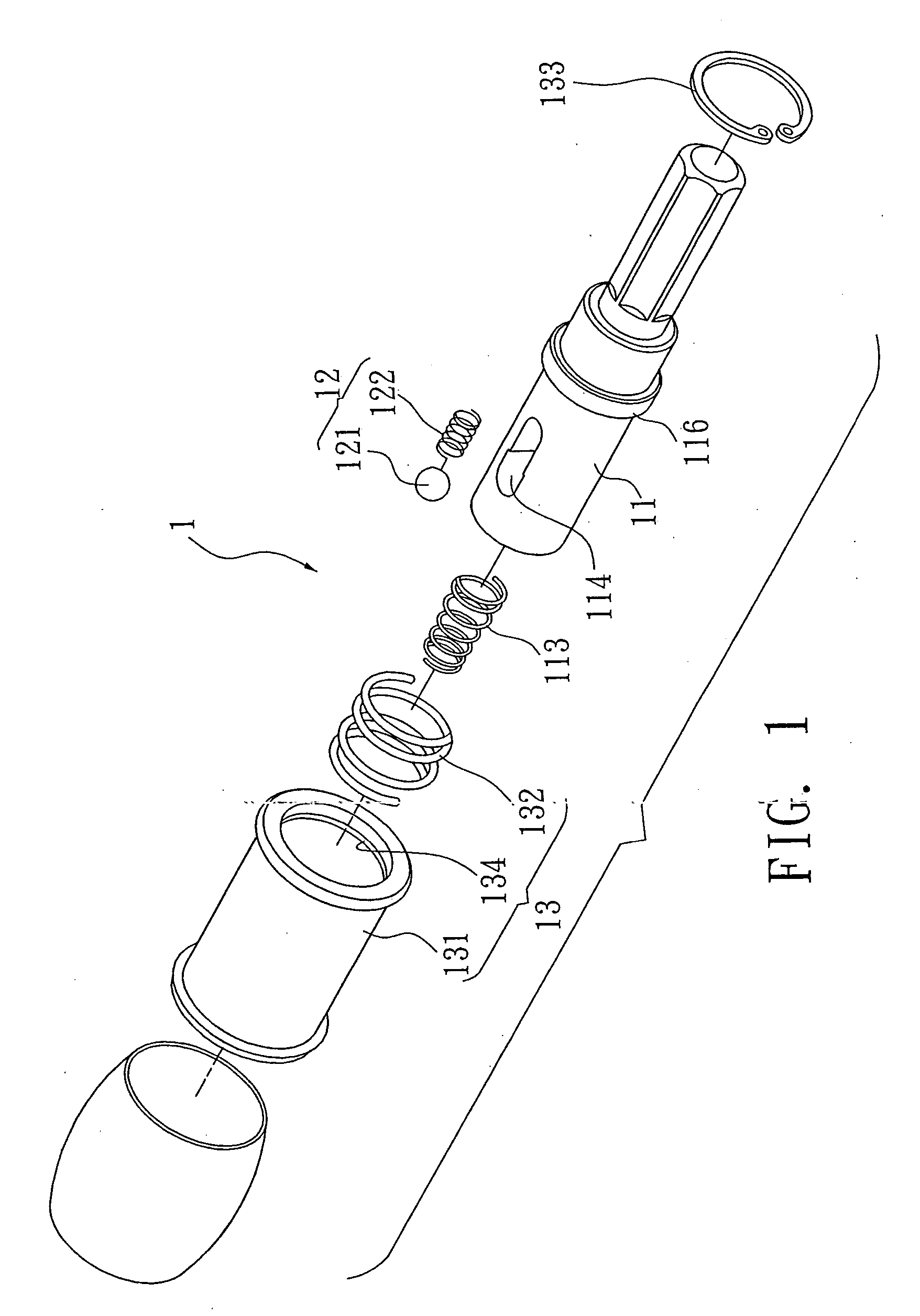
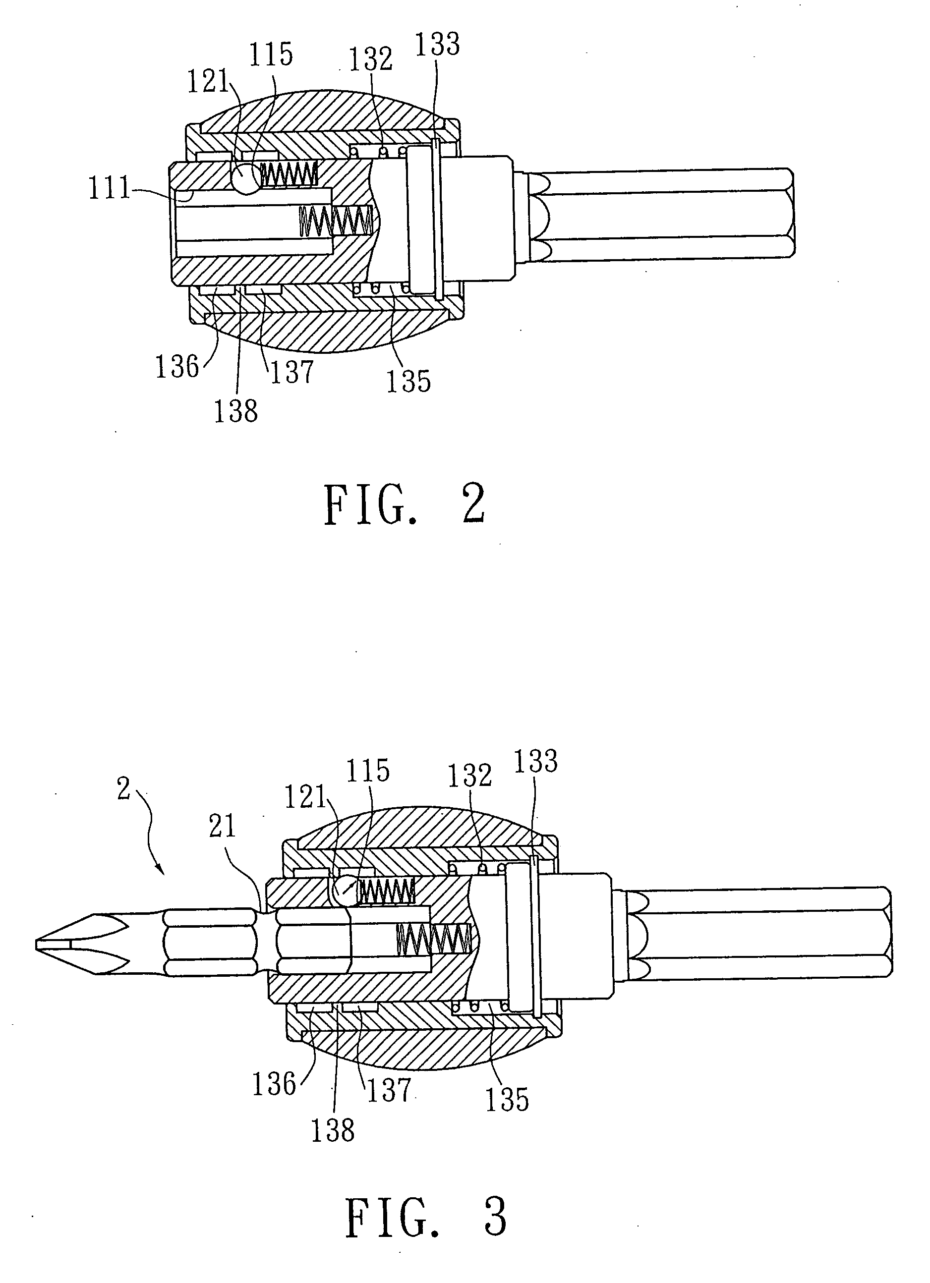
[0018] As illustrated, the preferred embodiment of the present invention relates to an improve construction of a screwdriver fast connector 1 comprised of a shank 11, a locking member 12, and a slide member 13. An insertions channel 111 is disposed to the shank 11 to receive insertion of a tip 2 of the screwdriver. An accommodation hole 112 is connected through the bottom of the insertion channel 111. The accommodation hole 112 is tightly engaged with a coil 113 and the coil 113 under normal conditions partially protrudes out of the accommodation hole 112 to produce the force need to eject the tip 2. An accommodation channel 114 is axially disposed to the outer edge of the shank 11, and a hole 115 penetrating through the shank 11 is dispose...


PUM


Abstract

A screwdriver fast connector is comprised of a shank including an insertion channel, an accommodation hole with a coil, an accommodation channel, and an elastic member penetrating the shank in radius; a locking member including a steel bead; and a slide member including a sleeve, an elastic member and a C-clamp, a first accommodation and a second accommodation spaces being provided to the sleeve; and the steel bead holding against a retaining part between both accommodation spaces so to fast mounting and removal of the tip by moving the steel bead.

Description

BACKGROUND OF THE INVENTION [0001] (a) Field of the Invention [0002] The present invention is related to a screwdriver fast connector, and more particularly, to one adapted with a locking member and a slide member to allow easy mounting, faster removal, and to be reliably locked when mounted to a tip of the screwdriver. [0003] (b) Description of the Prior Art [0004] As illustrated in FIGS. 6, and 8, a fast removal device of a screwdriver connector is essentially comprised of a flute 71 provided to a body 7 of the device to accommodate a coil 72 and a straight part 721 is left to be restricted in the flute 71 while being exposed out of an accommodation channel 73 to engage with a slot 81 from a tip 8. [0005] Accordingly, once the tip 8 is pushed into the accommodation channel 73, the straight part 721 is pushed towards the outer edge of the body 7. When the pressure disappears, the straight part 721 is inserted into the slot 81 of the tip 8 to secure the tip 8 in position. When a sli...

Claims


Application Information

Patent Timeline
Patent Type & Authority Applications(United States)
IPC IPC(8): B25B15/00B25B21/02B25B23/00
CPCB25B23/0035B25B15/001
Inventor HUANG, PING WEN
Owner HUANG PING WEN
Why Eureka
Try Eureka