
Adjustable paintball drop tube

a drop tube and paintball technology, applied in the field of paintball and drop tube, can solve the problems of increasing the use of paintball loaders, destroying the loader, and deprived the gun of ammunition, and achieve the effect of a wide range of different loaders

Inactive Publication Date: 2005-12-29
CHIPLEY JASON
View PDF11 Cites 24 Cited by
  • Summary
  • Abstract
  • Description
  • Claims
  • Application Information

AI Technical Summary

Benefits of technology

[0018] (d) It is another object of this invention to allow a greater ran

Problems solved by technology

Any mechanism that can be opened or loosened with a single movement of the hand, may also be loosened accidentally on the field by a single movement of some foreign object, thus releasing the loader from the gun, depriving the gun of ammunition and possibly destroying the loader in the fall.
Additionally, as the years have progressed the technology utilized in paintball loaders has increased as has the weight of the loaders filled with electronics and batteries, placing additional stresses on the junction between the paintball gun and the loader.
Both paths may provide some benefit but at an expense.
The O-rings are prone to wear, and at times are dislodged from the internal diameter of the drop tube and lodged in the inner workings of the paintball gun, while increased gripping pressure alone at times leads to applying excessive pressure which may actually crack the neck of the expensive loader.
Though certain prior art depicts various feed necks or drop tubes, no prior art known to the applicants describes an adjustable paintball drop tube that enables the drop tube itself to apply greater downward grip without an increase in the pounds of gripping force.
Further, no known prior art describes a feed neck or drop tube whatsoever utilizing helix retention segments.

Method used


Image

  • Adjustable paintball drop tube
  • Adjustable paintball drop tube

Examples


Embodiment Construction

—FIGS. 1 to 2

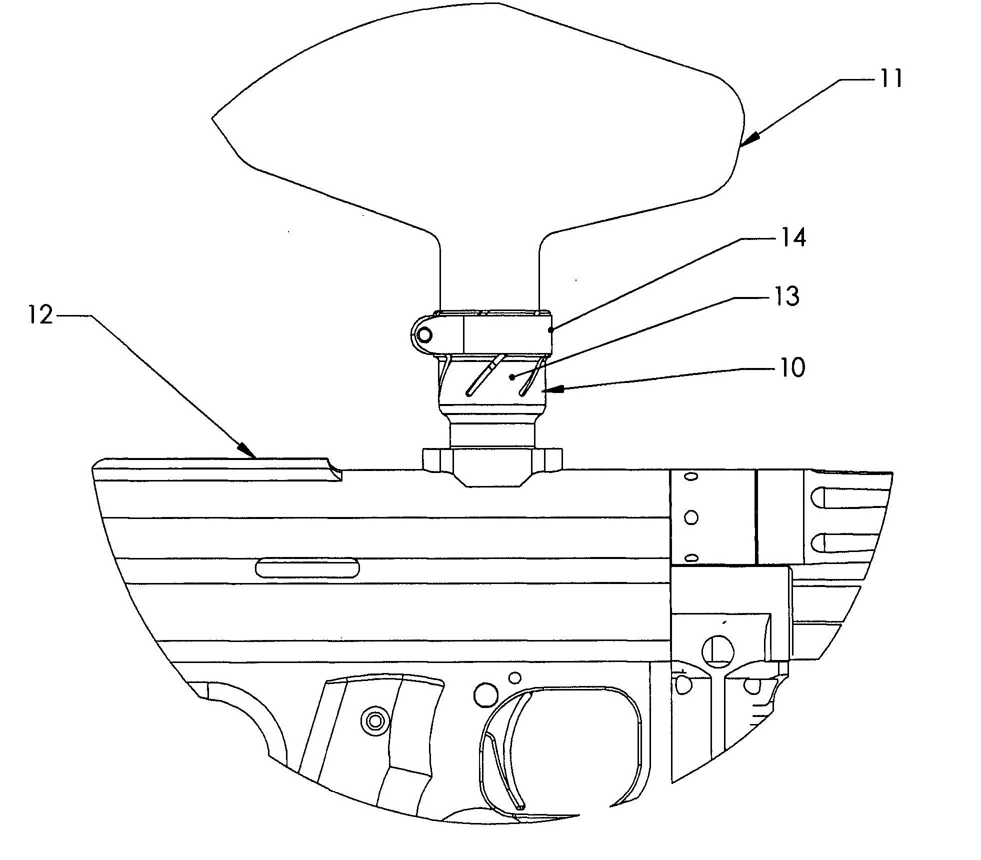
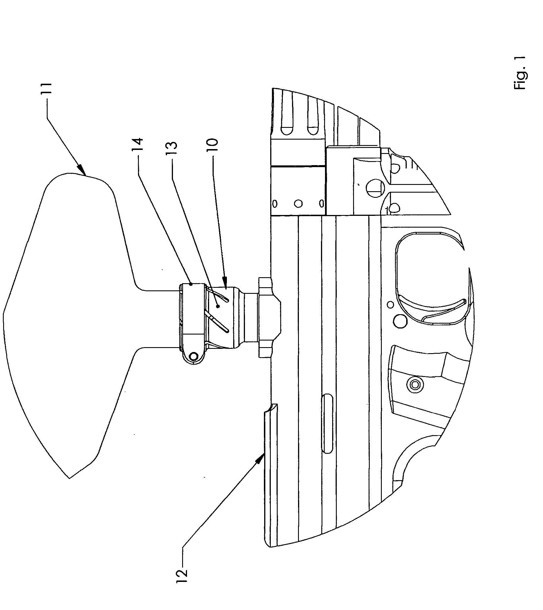
[0026] Now turning to the drawing it will be observed that it depicts a detailed drawing of one typical embodiment of improved adjustable paintball drop tube 10 with a paintball loader 11 atop a typical paintball gun 12. The helix retention segments 13 are compressed by clamp ring 14 and bite into the neck of the loader 11 retaining it atop the paintball gun 12.

OPERATION OF INVENTION FIGS. 1 to 2

[0027] The manner of using the is as follows in this preferred embodiment: the paintball drop tube of the invention 10 is threaded or otherwise installed into a paintball gun 12. A paintball loader 11 is placed within the open upper portion of the drop tube 10, the clamp ring 14 is compressed, in turn compressing the helix retention segments 13 which grip the loader 11, retaining it upon the top of the paintball gun 12.

CONCLUSION, RAMIFICATIONS AND SCOPE OF INVENTION

[0028] Thus the reader will see that improved adjustable paintball drop tube of this invention provides a new a...


PUM


Abstract

A improved adjustable paintball drop tube for use in conjunction with paintball guns and paintball loaders in paintball games and sports, wherein the improved adjustable paintball drop tube enables any of a variety of loaders to be adapted to any of a variety of paintball guns. Through the use of heliacal retention segments, the improved adjustable paintball drop tube also enables the user to more effectively retain paintball loaders throughout the vigorous activity inherent in the sport of paintball without said loader separating from the improved adjustable paintball drop tube, and thereby maintain a source of paintball ammunition for the paintball gun. The improved adjustable paintball drop tube can be formed of any of a variety of materials including molded plastic, aluminum or steel commonly used for such applications and known within the art.

Description

FIELD OF THE INVENTION [0001] This invention relates to the sport of paintball and paintball drop tube or “feed neck” components for adapting paintball “magazines” or “loaders” to paintball guns or “markers”, and more specifically this invention relates to an improved adjustable paintball drop tube. BACKGROUND OF THE INVENTION [0002] Paintball drop tubes began to see use as a distinct component on paintball guns around 1989, originally composed of plastic, and often relying on nothing more than a friction fit between the paintball gun on one side of the tube, and the loader on the other side. Originally these “tubes” were in fact elbows bent at an angle due to the angled feed port on the paintball guns of that era. Most paintball drop tubes or “feed necks” continued be composed of plastic for some years, although some employed a tightening means such as a screw and nut to tension one end or both ends of the drop tube. Even more recently, drop tubes began to be fashioned from aluminu...

Claims


Application Information

Patent Timeline
IPC IPC(8): F41B11/02F41F1/00
CPCF41B11/52
Inventor CHIPLEY, JASON
Owner CHIPLEY JASON
Learn More