Brake assembly

Inactive Publication Date: 2005-12-29
MERITOR HEAVY VEHICLE BRAKING SYST (UK) LTD
View PDF15 Cites 34 Cited by
  • Summary
  • Abstract
  • Description
  • Claims
  • Application Information

AI Technical Summary

Benefits of technology

[0015] An object of the present invention is to provide a bra

Problems solved by technology

Sliding caliper brakes for heavy road vehicles are necessarily themselves heavy.
Typically, the sliding caliper alone (in the absence of an associated carrier) will be so heavy that it is unsafe to be lifted by a single person alone (for example, during servicing) when the worn brake pads are replaced with new brak

Method used


Image

  • Brake assembly
  • Brake assembly
  • Brake assembly

Examples


Embodiment Construction

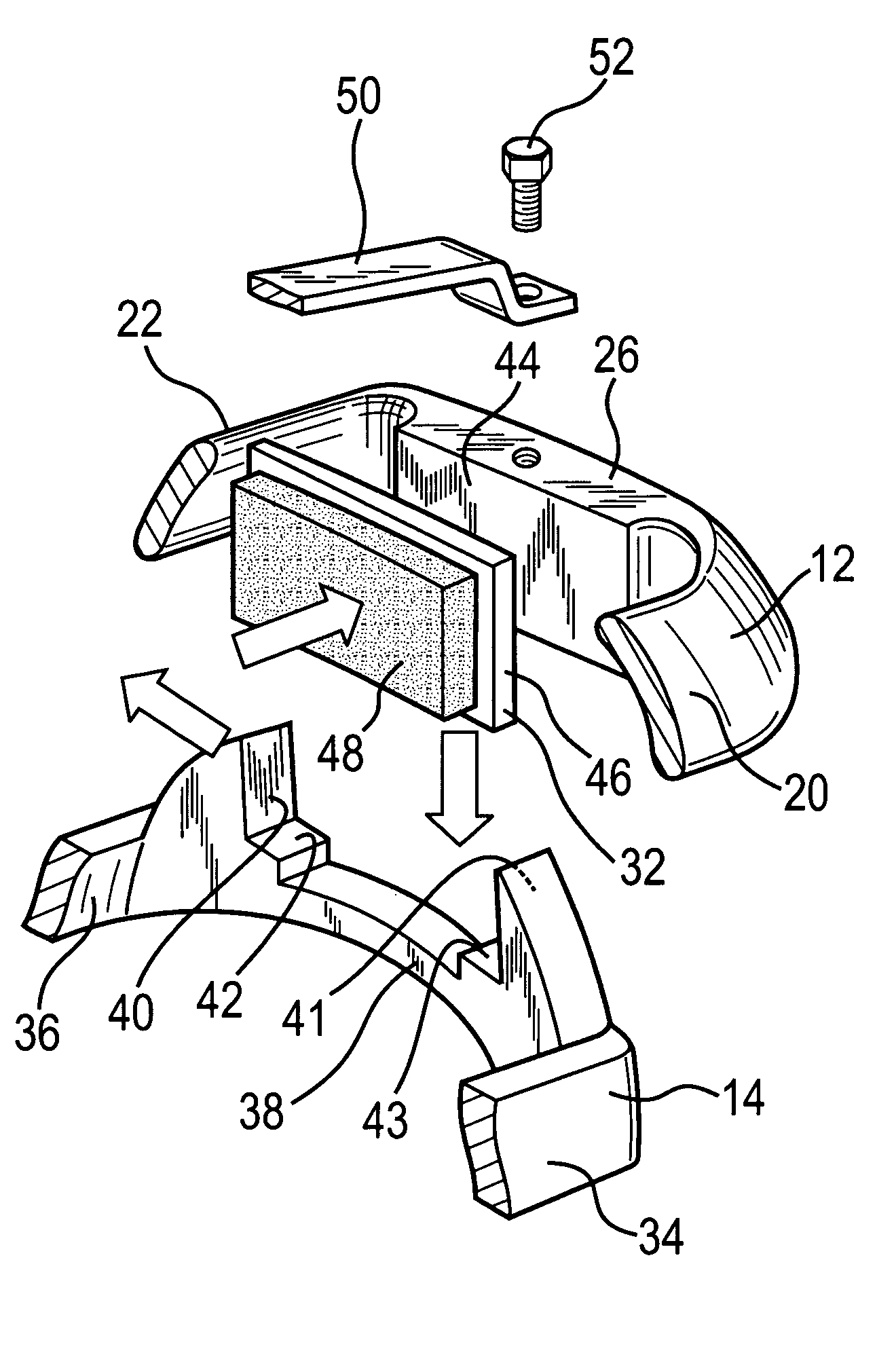
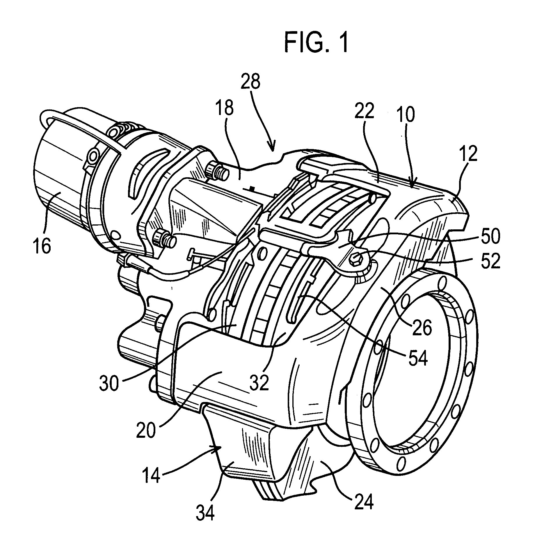
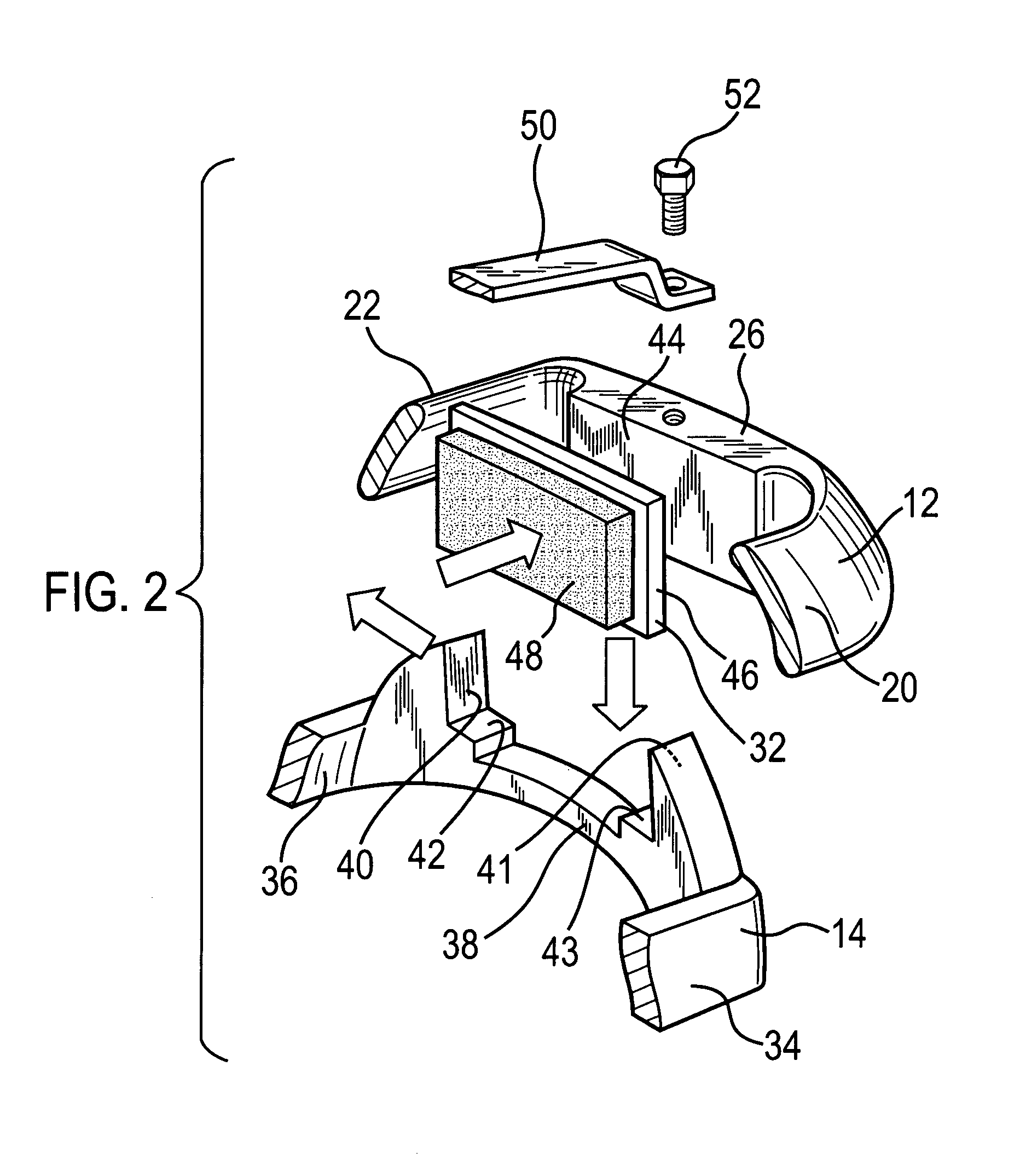
[0029] With reference to FIGS. 1 and 2, there is shown a known brake assembly 10 having a sliding caliper 12 and a carrier 14. The sliding caliper 12 includes an air chamber 16 fixed to an actuator housing 18 within which sits an actuator assembly (not shown).

[0030] The sliding caliper 12 further includes circumferentially spaced bridge arms 20 and 22 which are positioned radially outwardly of a brake disc 24. The sliding caliper 12 further has a reaction side portion 26 which connects ends of the bridge arms 20 and 22. The sliding caliper 12 is slideably mounted on pins (not shown) of the carrier 14.

[0031] In use, the carrier 14 will typically be secured to an axle of a heavy vehicle. A wheel hub is mounted on the end of the axle and rotationally secured to a wheel and a brake disc 24. The brake assembly 10 is arranged such that a reaction side portion 26 is at an outboard end of the axle, and the air chamber is positioned inboard of the reaction side portion 26. Thus, the actuat...


PUM


Abstract

A brake assembly includes a caliper having a first side portion connected to a second side portion by two circumferentially spaced bridge arms. The brake assembly includes a first brake pad and a second brake pad that are interchangeable and each having first and second circumferential ends. Each of the first and second brake pads have a pad formation remote from the first and second circumferential ends. The first brake pad is fitted in the first side portion of the caliper with the pad formation of the first brake pad engaging a caliper formation of the first portion side of the caliper for transferring braking torque loads from the first brake pad to the first side portion of the caliper. The second brake pad is fitted in the second side portion of the caliper with the first and second circumferential ends of the second brake pad engaging respective first and second circumferentially spaced abutments of the brake assembly for transferring braking torque loads from the second brake pad to the brake assembly.

Description

REFERENCE TO RELATED APPLICATIONS [0001] This application claims priority to Great Britain Patent Application 0414108.1 filed on Jun. 24, 2004. BACKGROUND OF THE INVENTION [0002] The present invention relates generally to a brake assembly, and in particular to a sliding caliper brake assembly or a brake assembly having a sliding disc for use on heavy road vehicles such as trucks, lorries, buses, etc. [0003] Brake calipers for motorcycles and cars are relatively light and are therefore easily handled by a single person. Accordingly, when replacing worn brake pads, it is acceptable to provide a design such that the brake caliper is removed, the worn brake pads are then replaced with new brake pads, and then the brake caliper is replaced. Such an arrangement is shown in U.S. Pat. No. 4,200,173. [0004] Sliding caliper brakes for heavy road vehicles are necessarily themselves heavy. Typically, the sliding caliper alone (in the absence of an associated carrier) will be so heavy that it is...

Claims


Application Information

Patent Timeline
IPC IPC(8): F16D55/226F16D55/36F16D65/092
CPCF16D55/226F16D55/36F16D2250/0084F16D2055/002F16D65/092
Inventor ROBERTS, PAULMORRIS, ROYSTON LEONARDGARGESHWARI, NAGARAJAMIRJI, PRADEEPUDUPI, KISHAN KUMARKUMBLE, RAJARAM
Owner MERITOR HEAVY VEHICLE BRAKING SYST (UK) LTD
Why Eureka
Try Eureka