Energy absorbing steering apparatus

a steering apparatus and energy absorption technology, applied in the direction of shock absorbers, elastic dampers, transportation and packaging, etc., can solve the problems of high manufacturing cost, insufficient energy absorption steering apparatus, and large size of steering apparatus

Inactive Publication Date: 2005-12-29
AISIN SEIKI KK
View PDF9 Cites 2 Cited by
  • Summary
  • Abstract
  • Description
  • Claims
  • Application Information

AI Technical Summary

Benefits of technology

[0008] According to an aspect of the present invention, an energy absorbing steering apparatus for a vehicle includes a support member for supporting a steering column by detachably attaching the steering column to a vehicle body and an energy absorption apparatus for relatively movably supporting the steering column relative to the vehicle body in a frontward direction of the vehicle body. The energy absorbing steering apparatus is designed for absorbing impact energy applied to the steering column. The energy absorption apparatus includes a support pin supported by the steering column, a first absorption member provided along the support pin and having a connection portion provided at one end of the first absorption member and connected to the vehicle body for applying load to the support pin when the support pin moves relative to the support member, a second absorption member provided along the support pin and having a connection portion provided at one end of the second absorption member and connected to the vehicle body for applying load to the support pin when the support pin moves relative to the support member, a connection member connected to the connection portion of the first absorption member and the connection portion of the second absorption member for connecting the first absorption member and the second absorption member to the vehicle body, and a control apparatus for controlling the connection member to change the number of absorption members connected to the vehicle body corresponding to a drive condition.

Problems solved by technology

Therefore, there is a danger that the energy absorption steering apparatus cannot sufficiently absorb the impact energy applied from the driver to the steering column.
Therefore, the motor tends to become larger size and cause high manufacturing cost.
As a result, the steering apparatus tends to be still larger size.

Method used


Image

  • Energy absorbing steering apparatus
  • Energy absorbing steering apparatus
  • Energy absorbing steering apparatus

Examples


first embodiment

[0025] the present invention will be explained with reference to drawing figures.

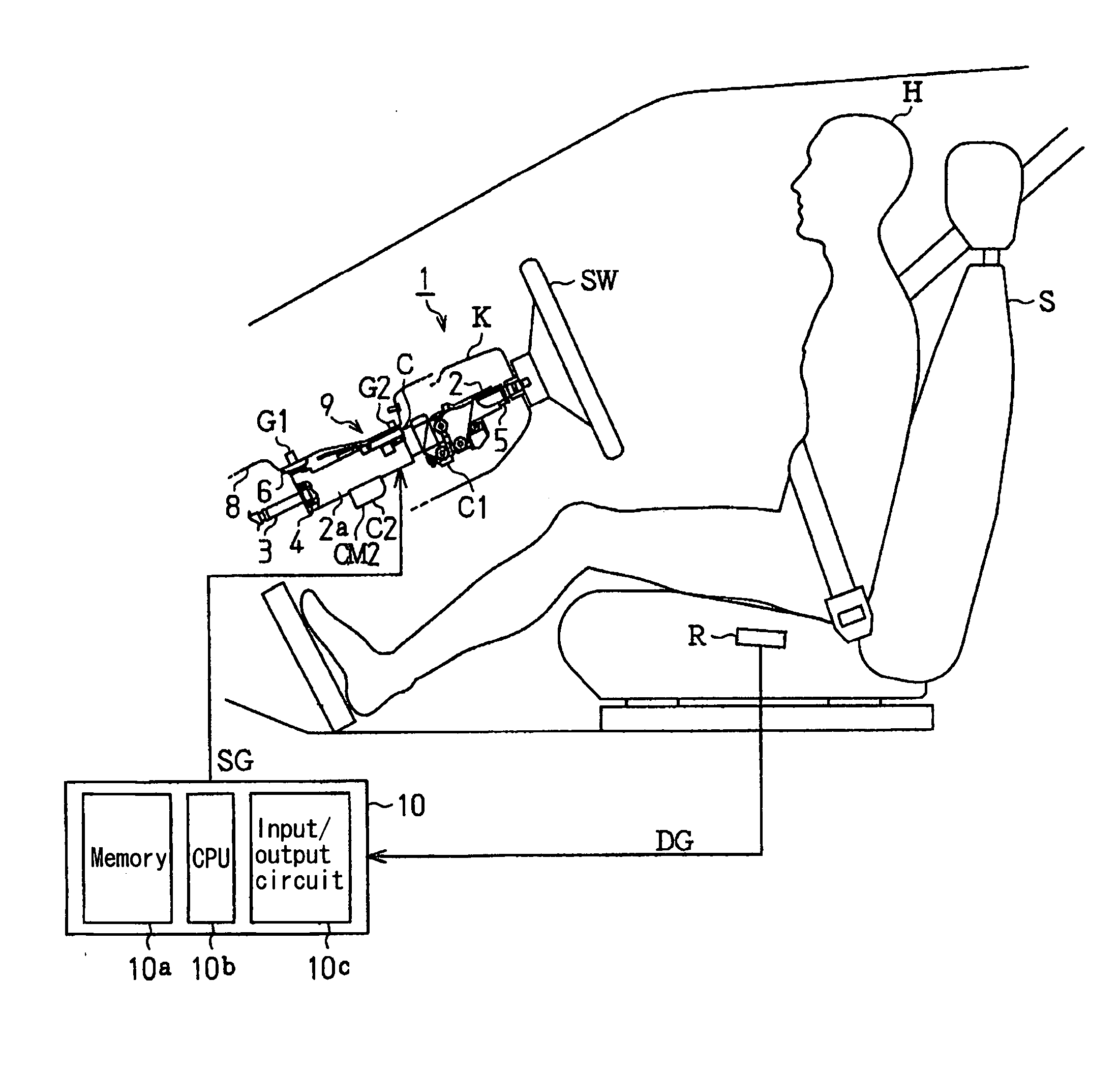
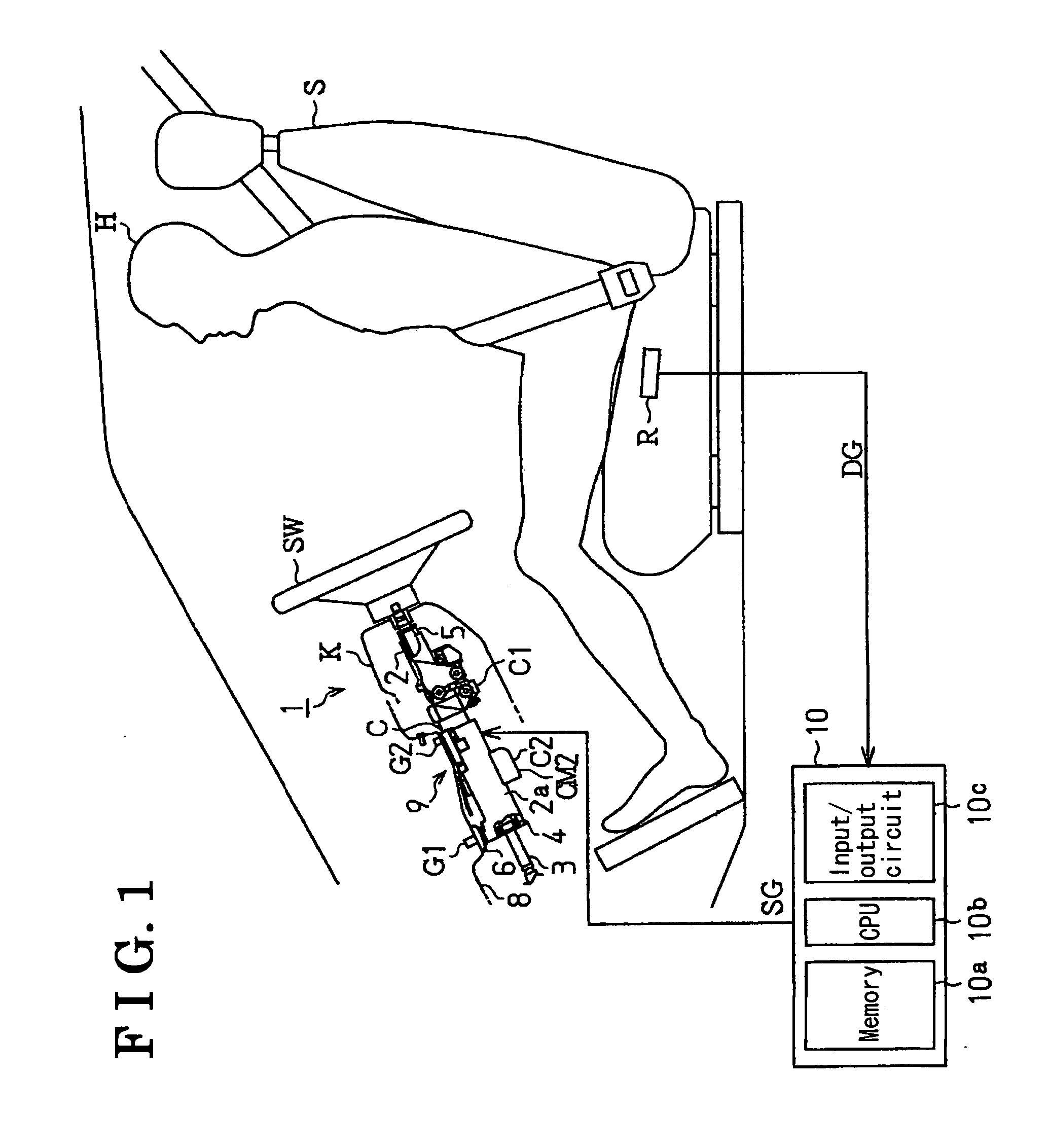
[0026]FIG. 1 represents a schematic side view illustrating an energy absorbing steering apparatus (referred to as a steering apparatus in later part) according to the embodiment of the present invention. As illustrated in FIG. 1, the steering apparatus 1 includes a steering column apparatus 2 (steering column) and a steering shaft 3 inserted into the steering column apparatus 2.

[0027] The steering column apparatus 2 is accommodated in a column cover K. The steering shaft 3 is rotatably supported by the steering column apparatus 2 through bearings 4 and 5. A steering link (not illustrated) is connected to the front end of the steering shaft 3. A steering wheel SW is attached to the rear end of the steering shaft 3. Here, and also in later part of this document, “front” and “rear” are determined relative to a vehicle.

[0028] Further, a column housing 2a is provided at approximately middle portion of the ...

third embodiment

[0074] As illustrated in FIG. 12, in the third embodiment, the energy absorption member 12 is configured from three absorption plates, that is, the first absorption plate 12A, the second absorption plate 12B, and a third absorption plate 12C. Then, the first absorption plate 12A includes the first hole H1a, the second hole H1b and a third hole H1c formed at the front of the hole H2b. Further, the second absorption plate 12B includes the hole H2 and a hole H2a formed at the front of the hole H2. Further, the third absorption plate 12C includes a base portion and a hole H3 formed at the base portion. Then, when the first absorption plate 12A, the second absorption plate 12B, and the third absorption plate 12C are overlapped together, as illustrated in FIG. 12, the hole H3 of the third absorption plate 12C is disposed so as to face the hole H2a of the second absorption plate 12B.

[0075] In addition, a second pin control apparatus 27 is secured on the lower wall 21 of the second support ...


PUM


Abstract

An energy absorbing steering apparatus for a vehicle includes a support member for supporting a steering column by detachably attaching the steering column to a vehicle body and an energy absorption apparatus for relatively movably supporting the steering column relative to the vehicle body in a frontward direction of the vehicle body. The energy absorbing steering apparatus is designed for absorbing impact energy applied to the steering column. The energy absorption apparatus includes a support pin supported by the steering column, a first absorption member provided along the support pin and having a connection portion provided at one end of the first absorption member and connected to the vehicle body for applying load to the support pin when the support pin moves relative to the support member, a second absorption member provided along the support pin and having a connection portion provided at one end of the second absorption member and connected to the vehicle body for applying load to the support pin when the support pin moves relative to the support member, a connection member connected to the connection portion of the first absorption member and the connection portion of the second absorption member for connecting the first absorption member and the second absorption member to the vehicle body, and a control apparatus for controlling the connection member to change the number of absorption members connected to the vehicle body corresponding to a drive condition.

Description

CROSS REFERENCE TO RELATED APPLICATIONS [0001] This application is based on and claims priority under 35 U.S.C. § 119 to Japanese Patent Application 2004-190401, filed on Jun. 28, 2004, the entire content of which is incorporated herein by reference. FIELD OF THE INVENTION [0002] This invention generally relates to an energy absorbing steering apparatus. BACKGROUND [0003] When a vehicle collides with another vehicle or a building, a driver of the vehicle collides with a steering apparatus by inertia force. Conventional energy absorbing steering apparatus includes an energy absorbing apparatus for absorbing the impact energy. [0004] In the energy absorbing steering apparatus of this kind, the steering column is movably supported relative to a vehicle body so that the steering column can move frontward relative to the vehicle when the driver of the vehicle collides with the steering apparatus. The energy absorbing steering apparatus further includes a member for absorbing the impact e...

Claims


Application Information

Patent Timeline
Patent Type & Authority Applications(United States)
IPC IPC(8): B62D1/19
CPCB62D1/195B62D1/19
Inventor ISHIBASHI, YOSHINORIOSHITA, MORITOINAYOSHI, HIDETOSHI
Owner AISIN SEIKI KK
Why Eureka
Try Eureka