Electrical connectors having differential signal pairs configured to reduce cross-talk on adjacent pairs

Inactive Publication Date: 2005-12-29
FCI AMERICAS TECH LLC +1
View PDF54 Cites 23 Cited by
  • Summary
  • Abstract
  • Description
  • Claims
  • Application Information

AI Technical Summary

Problems solved by technology

Often, the signal contacts are so closely spaced that undesirable interference, or “cross talk,” occurs between adjacent signal contacts.
Cross talk occurs when one signal contact induces electrical interference in an adjacent signal contact due to intermingling electrical fields, thereby compromising signal integrity.
Shields take up valuable space within the connector that could otherwise be used to provide additional signal contacts, and thus limit contact density (and, therefore, connector size).
Additionally, ma

Method used


Image

  • Electrical connectors having differential signal pairs configured to reduce cross-talk on adjacent pairs
  • Electrical connectors having differential signal pairs configured to reduce cross-talk on adjacent pairs
  • Electrical connectors having differential signal pairs configured to reduce cross-talk on adjacent pairs

Examples


Embodiment Construction

[0067] Certain terminology may be used in the following description for convenience only and should not be considered as limiting the invention in any way. For example, the terms “top,”“bottom,”“left,”“right,”“upper,” and “lower” designate directions in the figures to which reference is made. Likewise, the terms “inwardly” and “outwardly” designate directions toward and away from, respectively, the geometric center of the referenced object. The terminology includes the words above specifically mentioned, derivatives thereof, and words of similar import.

I-Shaped Geometry for Electrical Connectors—Theoretical Model

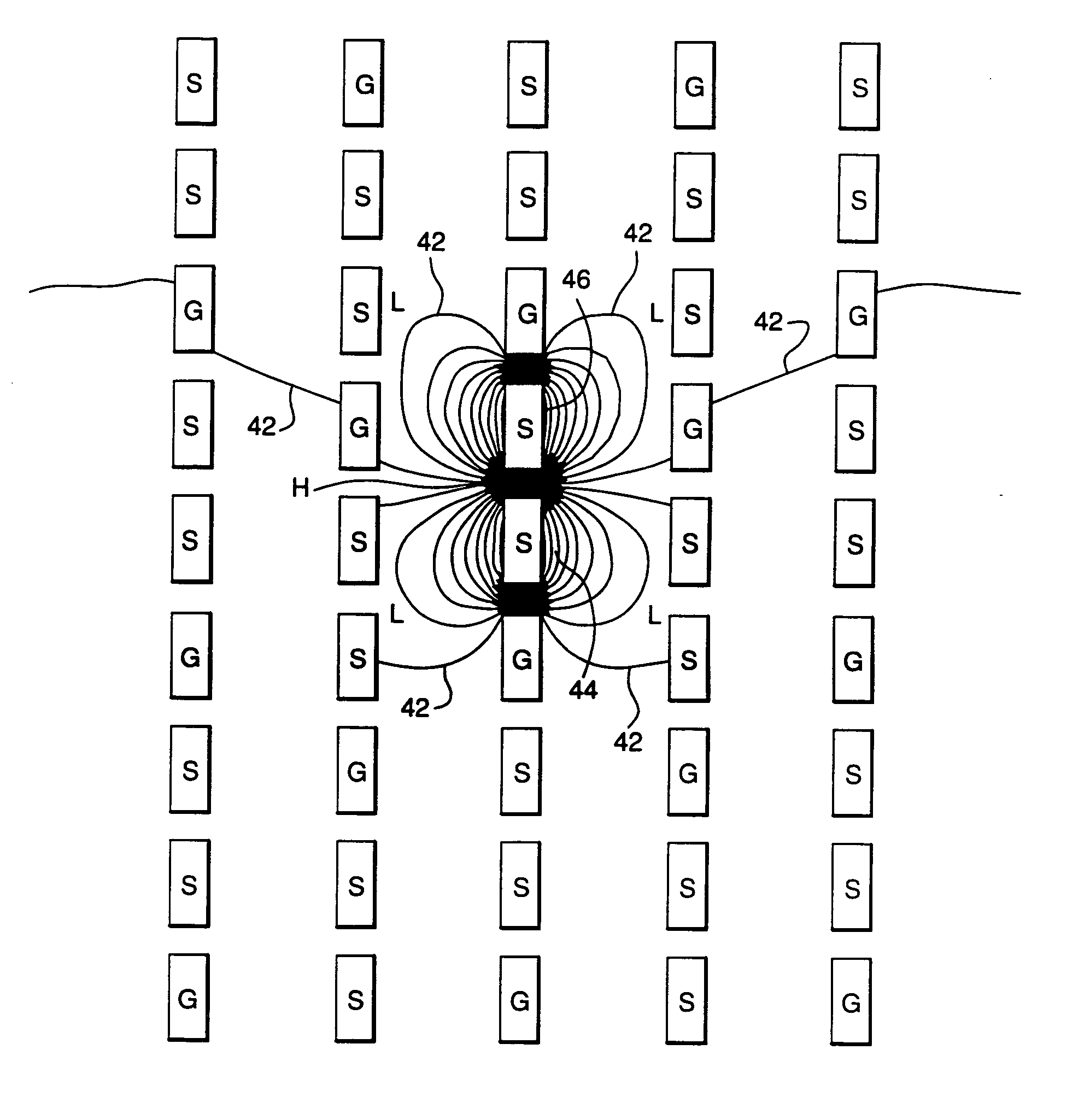
[0068]FIG. 2A is a schematic illustration of an electrical connector in which conductive and dielectric elements are arranged in a generally “I” shaped geometry. Such connectors are embodied in the assignee's “I-BEAM” technology, and are described and claimed in U.S. Pat. No. 5,741,144, entitled “Low Cross And Impedance Controlled Electric Connector,” the disclosure of wh...


PUM


Abstract

An electrical connector according to the invention may include a first signal contact that defines a first side and a first edge, wherein the first side is greater in length than the first edge, the first edge having a first edge width, and a second signal contact that defines a second side and a second edge, wherein the second side is greater in length that the second edge, the second edge having a second edge width. The first signal contact and the second signal contact may be positioned edge-to-edge. A gap may be defined between the first edge of the first signal contact and the second edge of the second signal contact. The gap may have a gap width that is approximately equal to at least one of the first edge width and the second edge width. The connector may have a column pitch, and the gap width may be based on the column pitch. The gap width may be approximately 0.3-0.4 millimeters.

Description

CROSS-REFERENCE TO RELATED APPLICATIONS [0001] This application is a continuation of U.S. patent application Ser. No. 10 / 634,547, filed Aug. 5, 2003, which is a continuation-in-part of U.S. patent application Ser. No. 10 / 294,966, filed Nov. 14, 2002, which is a continuation-in-part of each of U.S. patent application Ser. No. 09 / 990,794, filed Nov. 14, 2001, now U.S. Pat. Nos. 6,692,272, and 10 / 155,786, filed May 24, 2002, now U.S. Pat. No. 6,652,318. The content of each of the above-referenced U.S. patents and patent applications is incorporated by reference herein in its entirety.FIELD OF THE INVENTION [0002] Generally, the invention relates to the field of electrical connectors. More particularly, the invention relates to electrical connectors having contacts that may be selectively designated as either ground or signal contacts such that, in a first designation, the contacts form at least one differential signal pair, and, in a second designation, the contacts form at least one s...

Claims


Application Information

Patent Timeline
IPC IPC(8): H01R4/66H01R12/16H01R13/502H01R13/6471H01R13/648H01R13/658H01R13/6585H01R29/00
CPCH01R29/00H01R12/52Y10S439/941H01R13/6587H01R13/6471H01R13/6477H01R12/724H01R4/66
Inventor MINICH, STEVEN E.SHUEY, JOSEPH B.HULL, GREGORY A.SMITH, STEPHEN
Owner FCI AMERICAS TECH LLC
Why Eureka
Try Eureka