Kitchen utensil and method of manufacture

Inactive Publication Date: 2006-01-05
FUERITECHNICS GROUP
View PDF8 Cites 15 Cited by
  • Summary
  • Abstract
  • Description
  • Claims
  • Application Information

AI Technical Summary

Benefits of technology

[0007] It is the prime object of the present invention to form a utensil having a tang which constitutes a substantial portion of the utensil handle,

Problems solved by technology

The traditional knife handles, with two handle halves riveted to the central spine, suffer from loosening of the rivets (a durability problem) and/or opening up of the handle gaps (a hygiene problem).
More modern handle types, li

Method used


Image

  • Kitchen utensil and method of manufacture
  • Kitchen utensil and method of manufacture
  • Kitchen utensil and method of manufacture

Examples


Embodiment Construction

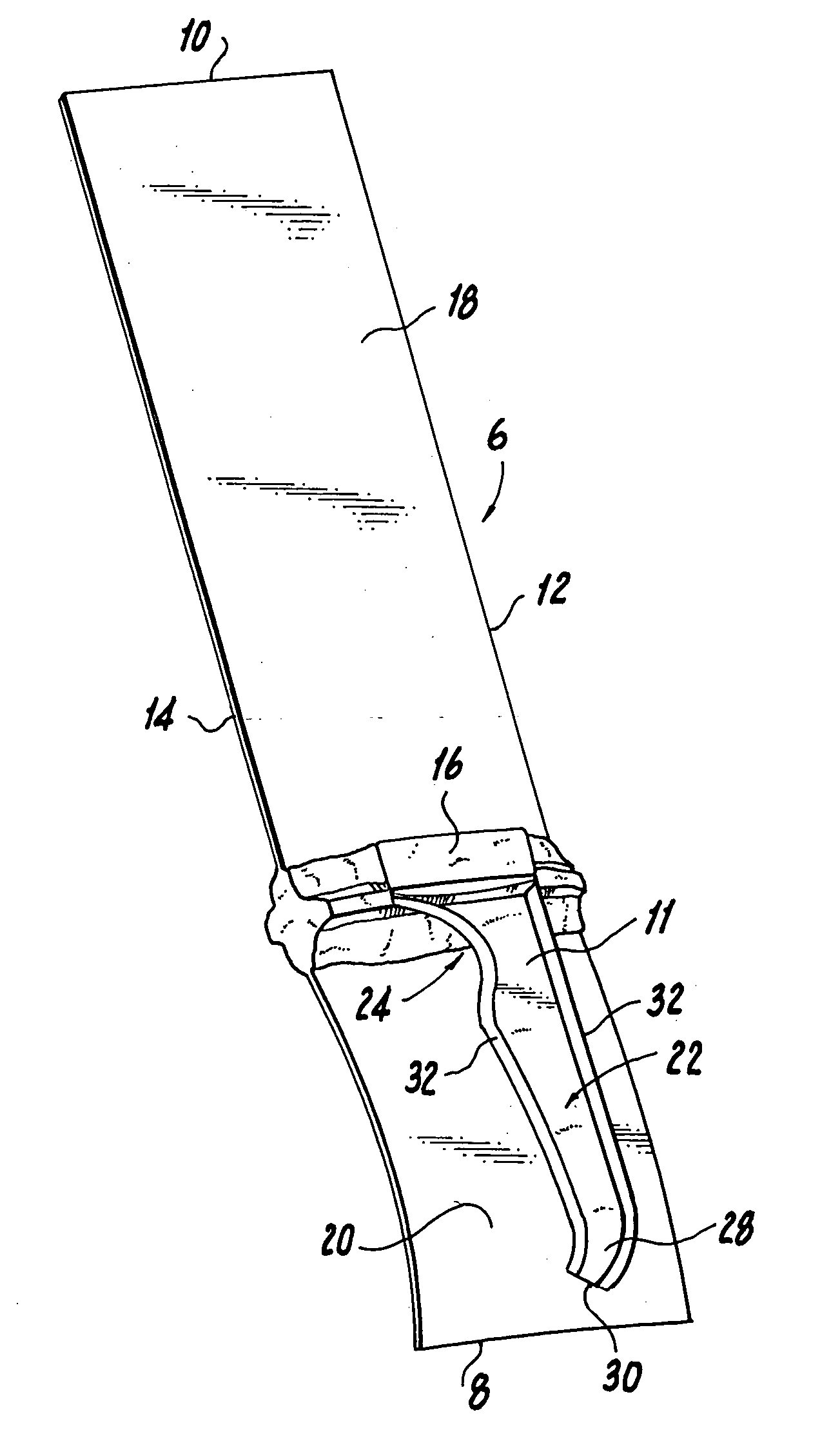
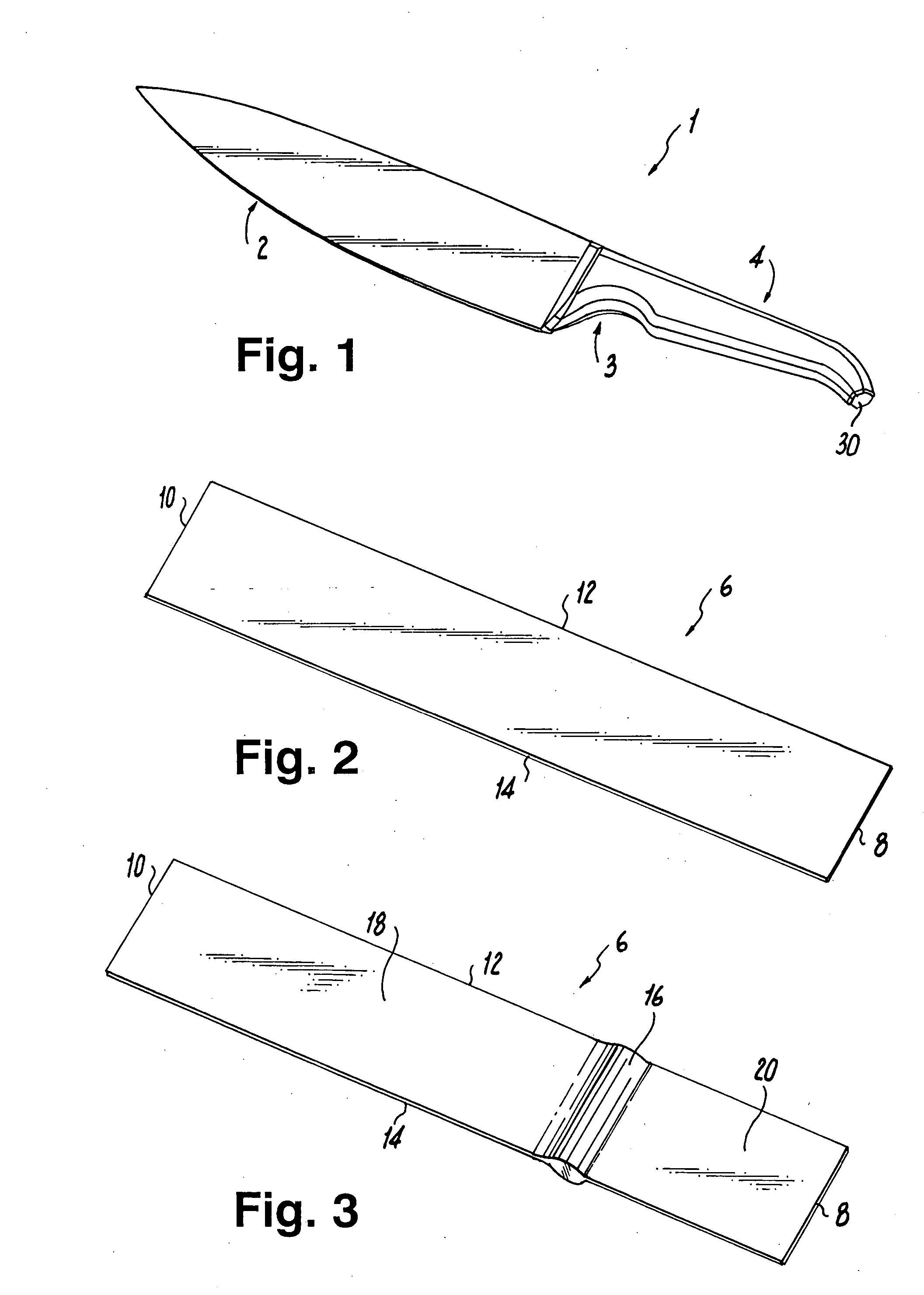
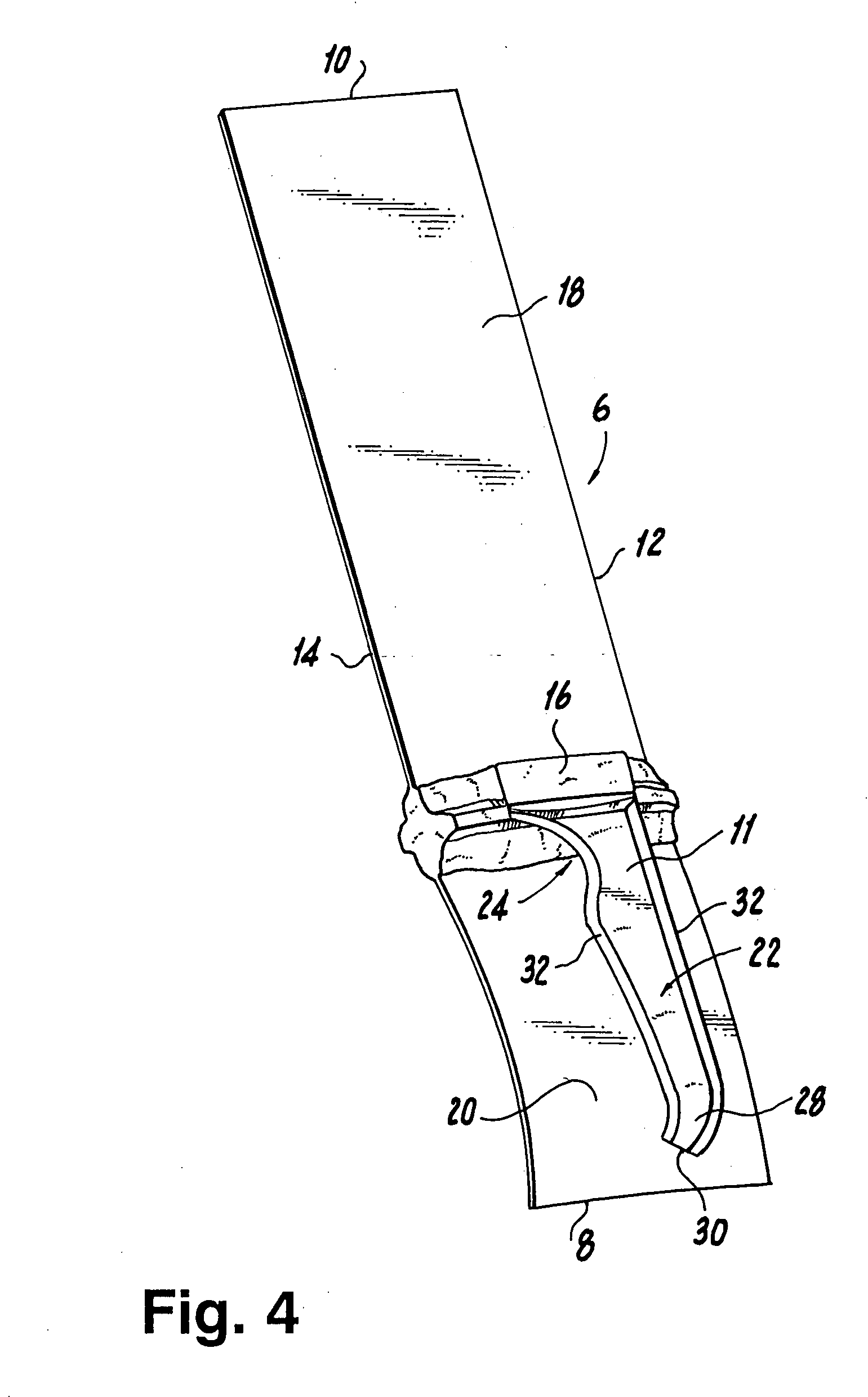
[0020] A kitchen utensil generally designated 1 is here shown in the form of a knife having a working part or blade 2 and a handle 4. It is formed primarily from a single sheet 6 (see FIG. 2) of an appropriate material such as, particularly in the case of the knife, structural metal of appropriate physical characteristics. The sheet 6 has rearward and forward edges 8 and 10 and side edges 12 and 14. The length and width of the sheet 6 corresponds roughly to the length and width of the desired utensil. The thickness of the sheet 6 is correspondingly chosen to provide the desired physical characteristics of the end product.

[0021] As shown in FIG. 3, a bolster 16 may be molded into the knife and serve as a traditional structure between the sections 18 and 20 which will ultimately become the blade 2 and the major portion of the handle 4 of the utensil, respectively. This may be formed by squeezing the material toward the middle to form a solid bulge. The bolster 16 helps to withstand t...


PUM


Abstract

An improved utensil such as a knife is produced by forming integrally with the blade or other working part a tang which ultimately constitutes a substantial portion of the knife-handle including the outer hand-engaged surface of the handle, and providing the tang with an attached cover which constitutes the remainder of the utensil handle.

Description

[0001] The present invention relates to a novel construction for a kitchen utensil such as a knife and to a method of manufacturing such an object. [0002] Applicant claims priority with respect to Australian Provisional Application Serial No. 2003903938 filed 29 Jul. 2003 entitled “KNIVES”. BACKGROUND OF THE INVENTION [0003] The invention is here specifically disclosed in connection with a utensil having a working part such as a knife blade fixed to a handle. Knives of the applicable type include, without limitation, kitchen knives, butter knives, chef's knives, sporting knives, letter-openers, and bodkins and the like. [0004] The main components of a conventional fixed blade knife are a working part or blade, a tang and a handle. With many traditional knives, the tang is forged with the blade and forms the center spine of the handle, with other handle parts being riveted, pressed, molded, or welded onto both sides of the tang. The traditional knife handles, with two handle halves r...

Claims


Application Information

Patent Timeline
IPC IPC(8): B21K11/00B26B29/00
CPCB21D53/64B26B3/00B21K11/02
Inventor HENRY, MARK JAMES
Owner FUERITECHNICS GROUP
Why Eureka
Try Eureka