Formation evaluation system and method

a technology of formation evaluation and evaluation system, applied in the field of formation evaluation system and method, can solve the problems of fluid that is generally unacceptable for hydrocarbon fluid sampling and/or evaluation, difficult to avoid contamination, and various challenges

Inactive Publication Date: 2006-01-05
SCHLUMBERGER TECH CORP
View PDF98 Cites 76 Cited by
  • Summary
  • Abstract
  • Description
  • Claims
  • Application Information

AI Technical Summary

Benefits of technology

[0058] Presently preferred embodiments of the invention are shown in the above-identified figures and described in detail below. In describing the preferred embodiments, like or identical reference numerals are used to identify common or similar elements. The figures are not necessarily to scale and certain features and certain views of the figures may be shown exaggerated in scale or in schematic in the interest of clarity and conciseness.
[0025]FIG. 1 is a schematic view of a subsurface formation penetrated by a wellbore lined with mudcake, depicting the virgin fluid in the subsurface formation.

Problems solved by technology

Various challenges may arise in the process of obtaining virgin fluid from subsurface formations.
This material often contaminates the virgin fluid as it passes through the borehole, resulting in fluid that is generally unacceptable for hydrocarbon fluid sampling and / or evaluation.
Such fluid is referred to herein as “contaminated fluid.” Because fluid is sampled through the borehole, mudcake, cement and / or other layers, it is difficult to avoid contamination of the fluid sample as it flows from the formation and into a downhole tool during sampling.
A challenge thus lies in minimizing the contamination of the virgin fluid during fluid extraction from the formation.
The challenge remains in adapting to the flow of the fluid so that the virgin fluid is collected in the downhole tool during sampling.
However, it has been discovered that when the formation fluid passes into the downhole tool, various contaminants, such as wellbore fluids and / or drilling mud, may enter the tool with the formation fluids.
These contaminates may affect the quality of measurements and / or samples of the formation fluids.
Moreover, contamination may cause costly delays in the wellbore operations by requiring additional time for more testing and / or sampling.
Additionally, such problems may yield false results that are erroneous and / or unusable.

Method used


Image

  • Formation evaluation system and method
  • Formation evaluation system and method
  • Formation evaluation system and method

Examples


Embodiment Construction

[0058] Presently preferred embodiments of the invention are shown in the above-identified figures and described in detail below. In describing the preferred embodiments, like or identical reference numerals are used to identify common or similar elements. The figures are not necessarily to scale and certain features and certain views of the figures may be shown exaggerated in scale or in schematic in the interest of clarity and conciseness.

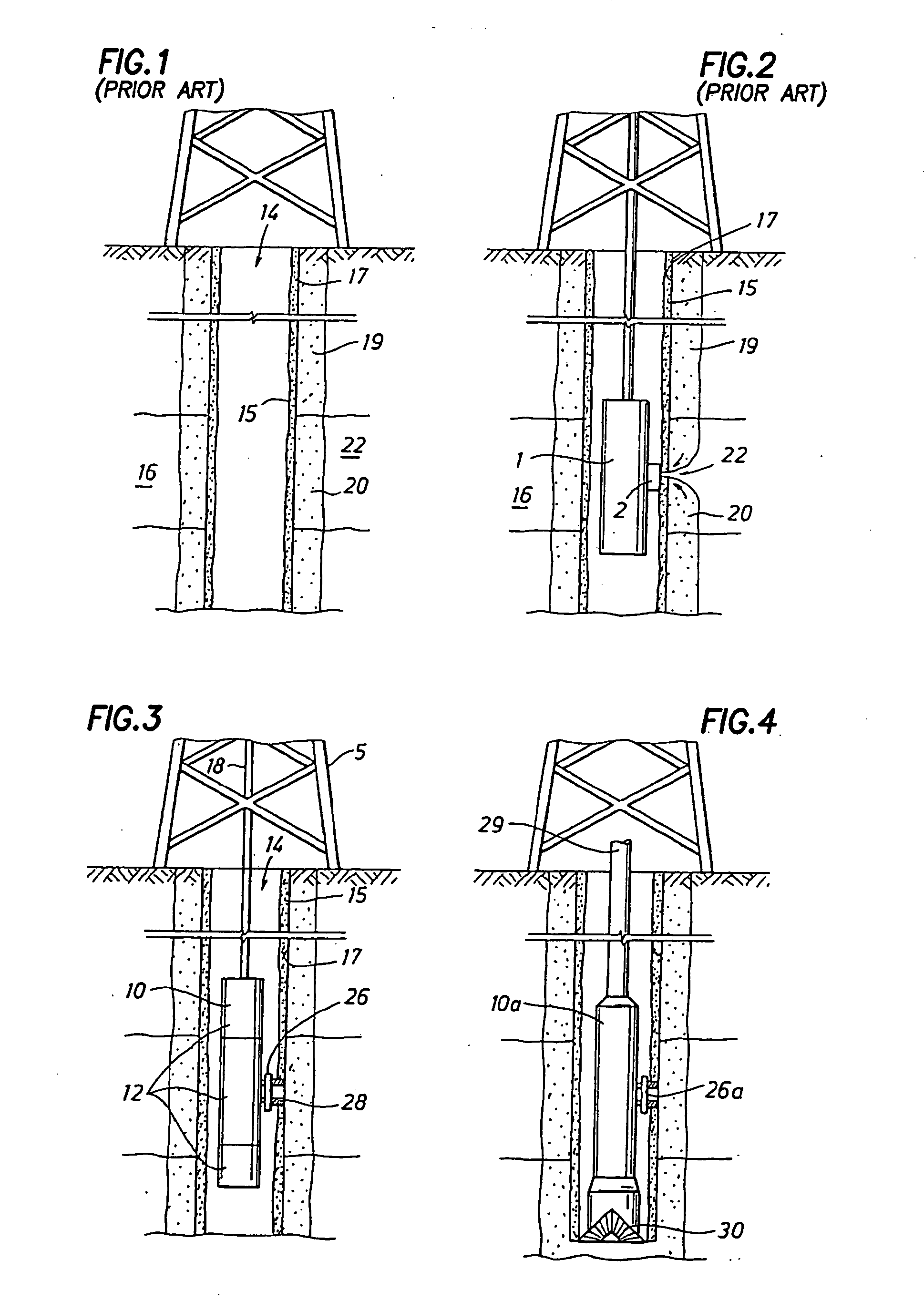
[0059] Referring to FIG. 3, an example environment within which the present invention may be used is shown. In the illustrated example, the present invention is carried by a down hole tool 10. An example commercially available tool 10 is the Modular Formation Dynamics Tester (MDT) by Schlumberger Corporation, the assignee of the present application and further depicted, for example, in U.S. Pat. Nos. 4,936,139 and 4,860,581 hereby incorporated by reference herein in their entireties.

[0060] The downhole tool 10 is deployable into bore hole 14 and...


PUM


Abstract

A method of evaluating a fluid from a subterranean formation drawn into a downhole tool positioned in a wellbore penetrating the subterranean formation is provided. The method involves drawing fluid from a formation into an evaluation flowline, drawing fluid from a formation into a cleanup flowline, measuring a property of the fluid in the evaluation flowline and detecting stabilization of the property of the fluid in the evaluation flowline. Fluid properties in a combined flowline may be generated from the evaluation and cleanup flowlines. The fluid properties of the combined flowline may be used to project future evaluation flowline fluid properties. Contamination levels for a given fluid property of a given flowline may also be determined.

Description

CROSS-REFERENCE TO RELATED APPLICATIONS [0001] This application is a continuation-in-part of U.S. application Ser. No. 10 / 711,187, filed on Aug. 31, 2004 and U.S. application Ser. No. 11 / 076,567 filed on Mar. 9, 2005 which is a divisional of U.S. application Ser. No. 10 / 184,833, filed Jun. 28, 2002.BACKGROUND OF THE INVENTION [0002] 1. Field of the Invention [0003] The present invention relates to techniques for performing formation evaluation of a subterranean formation by a downhole tool positioned in a wellbore penetrating the subterranean formation. More particularly, the present invention relates to techniques for reducing the contamination of formation fluids drawn into and / or evaluated by the downhole tool. [0004] 2. Background of the Related Art [0005] Wellbores are drilled to locate and produce hydrocarbons. A downhole drilling tool with a bit at and end thereof is advanced into the ground to form a wellbore. As the drilling tool is advanced, a drilling mud is pumped throug...

Claims


Application Information

Patent Timeline
Patent Type & Authority Applications(United States)
IPC IPC(8): E21B41/02E21BE21B49/00E21B49/08E21B49/10
CPCE21B49/10E21B49/08G01N21/534
Inventor ZAZOVSKY, ALEXANDER F.CAMPO, CHRISTOPHER S. DELVASQUES, RICARDO
Owner SCHLUMBERGER TECH CORP
Why Eureka
Try Eureka