Surgical stapling system

a stapling system and surgical technology, applied in the direction of surgical staples, prostheses, blood vessels, etc., can solve the problems of time-consuming and difficult suturing process of grafts to the aorta or the cu

Inactive Publication Date: 2006-01-05
DATASCOPE INVESTMENT
View PDF33 Cites 242 Cited by
  • Summary
  • Abstract
  • Description
  • Claims
  • Application Information

AI Technical Summary

Benefits of technology

[0013] The surgical stapler may further include a control mechanism operable

Problems solved by technology

The suturing of the graft to the aorta or the cuff can be a difficult and time-consuming

Method used


Image

  • Surgical stapling system
  • Surgical stapling system
  • Surgical stapling system

Examples


Embodiment Construction

[0062] In the detailed description which follows, the features of the present invention will be described in connection with the anastomosis of a prosthetic graft to the aorta, such as may be performed in the repair of an abdominal aortic aneurysm. It will be appreciated, however, that the various features of the present invention may be readily utilized to connect a tubular prosthetic graft to any body lumen. Each of the various components of the surgical stapling system of the present invention is described in separate headings below.

Prosthetic Graft

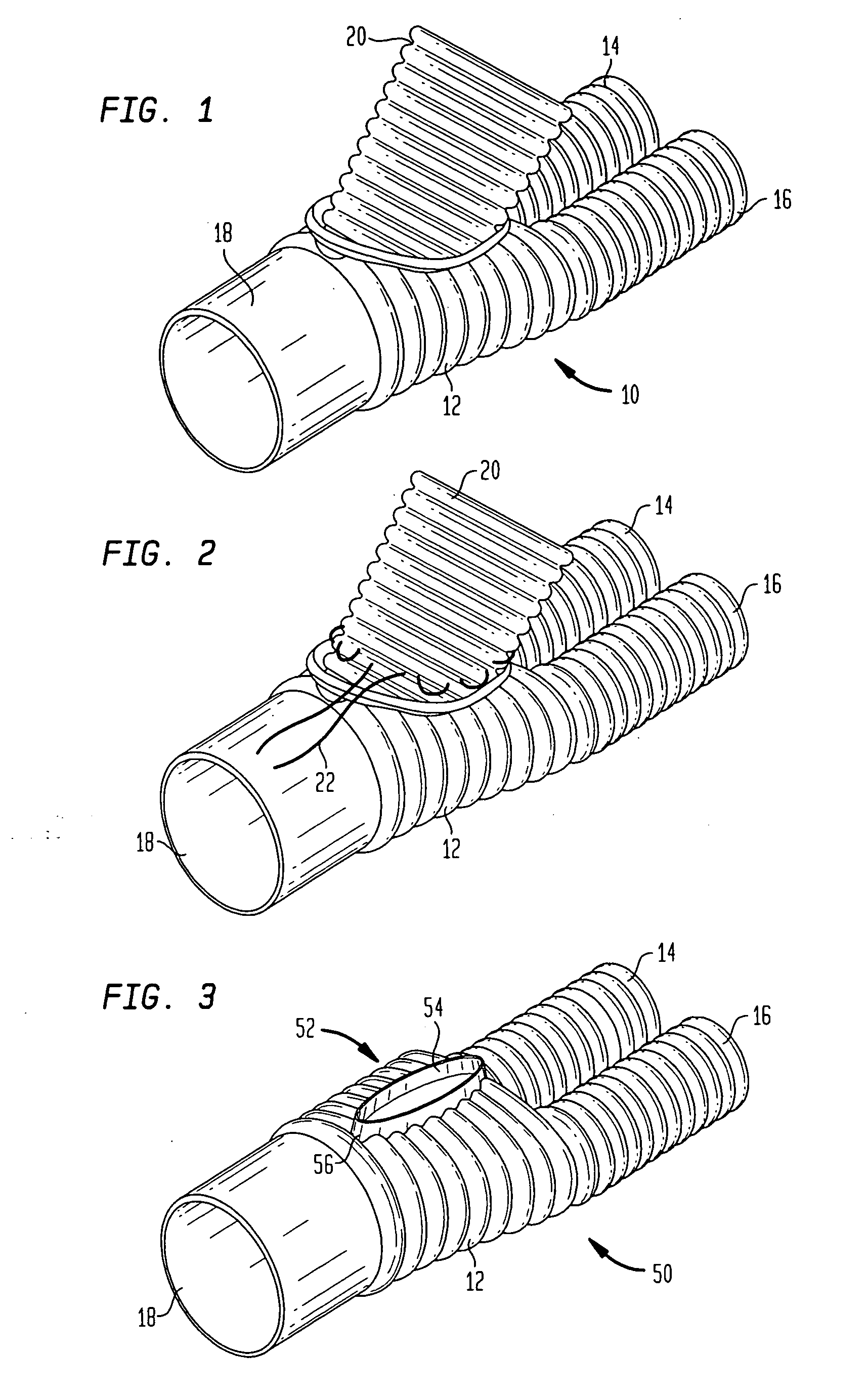
[0063] Referring to FIG. 1, there is illustrated one preferred embodiment of a prosthetic graft 10 for use in the present invention. Graft 10 is a hollow generally Y-shaped structure formed by a tapered main body 12 which branches into two legs 14 and 16. Legs 14 and 16 may have a generally cylindrical shape with a substantially uniform diameter from their juncture with main body 12 to their respective free ends. Opposite legs 14 an...


PUM

PropertyMeasurementUnit
Thicknessaaaaaaaaaa
Diameteraaaaaaaaaa
Flexibilityaaaaaaaaaa

Abstract

A system is provided for joining two tubular structures by a surgical stapling procedure. The system includes a series of sizers, a specifically designed graft, a loading unit, a wand, a surgical loop and a stapling instrument. The sizers are for determining the diameter of a target aorta and the availability of a sufficient transected aortic length to perform a stapling procedure. The loading unit holds the graft in position in the body and deploys a circumferential line of staples through the graft and an overlapping end of the aorta. The graft may include a side port by which the loading unit holds the graft during the stapling procedure, and which may be closed once the stapling procedure has been completed. The wand may be used to introduce the loading unit and graft into the body, to position them within the transected aorta, and to hold them in place during the application of the surgical loop. The surgical loop may include a band formed from a flexible material and having a width greater than its thickness so as to facilitate the formation of an annular loop. With the surgical loop holding the aorta and graft in relative overlapping positions, the wand may be removed from the loading unit and the stapling instrument may be assembled thereto. The stapling instrument includes a plurality of anvils which may be closed to form a circle overlying the aorta, and a trigger mechanism for firing the staples. When fired, the staples are deployed radially outward through the graft and aorta, whereupon their free ends are bent inwardly by staple returns on the anvils. As a result, a plurality of staples may be simultaneously deployed quickly and accurately in a circumferential pattern so as to join together two tubular structures. The system may be used in either an open surgical procedure or laparascopically.

Description

CROSS-REFERENCE TO RELATED APPLICATIONS [0001] The present application claims the benefit of U.S. Provisional Patent Application Ser. No. 60 / 571,738 filed May. 17, 2004, the disclosure of which is hereby incorporated by reference herein.BACKGROUND OF THE INVENTION [0002] The present invention relates generally to a surgical stapling system, and more particularly to a system for joining two tubular structures using surgical staples. Still more particularly, the present invention relates to an apparatus and method for stapling together two tubular structures either through an open surgical procedure or laparoscopically. [0003] The repair of aortic aneurysms and other aortic defects typically requires major abdominal surgery in which the defective segment of the aorta is removed and replaced with a prosthetic device, such as a synthetic graft. Such procedure ordinarily requires the graft to be sutured to the end of the sectioned aorta or to a felt cuff which has been sutured to the aor...

Claims


Application Information

Patent Timeline
IPC IPC(8): A61B17/04A61B17/072A61B17/115A61B17/12A61F2/06
CPCA61B17/072A61B17/115A61B17/1155A61B17/12013A61F2002/9517A61B2017/1157A61F2/06A61F2002/061A61F2002/065A61B2017/1107A61F2/9517
Inventor FONTAYNE, DIEGO Y.
Owner DATASCOPE INVESTMENT
Why Eureka
Try Eureka