Symmetrical phase shifting fork transformer

a phase shifting fork transformer and symmetrical technology, applied in transformers, transformer/inductance details, electrical equipment, etc., can solve the problems of generating undesired current in outputs, affecting the operation of transformers, and patents that do not disclose or teach ordinary skill the details of mechanical structures

Inactive Publication Date: 2006-01-05
MAZUR ALEXANDER +1
View PDF4 Cites 21 Cited by
  • Summary
  • Abstract
  • Description
  • Claims
  • Application Information

AI Technical Summary

Problems solved by technology

However, this patent does not disclose or teach one of ordinary skill the details of the mechanical structure of the associated transformer used with the disclosed windings.
Without the delta winding the triplin harmonics would generate undesired currents in the outputs and detrimentally affect the operation of the transformer.

Method used


Image

  • Symmetrical phase shifting fork transformer
  • Symmetrical phase shifting fork transformer
  • Symmetrical phase shifting fork transformer

Examples


Embodiment Construction

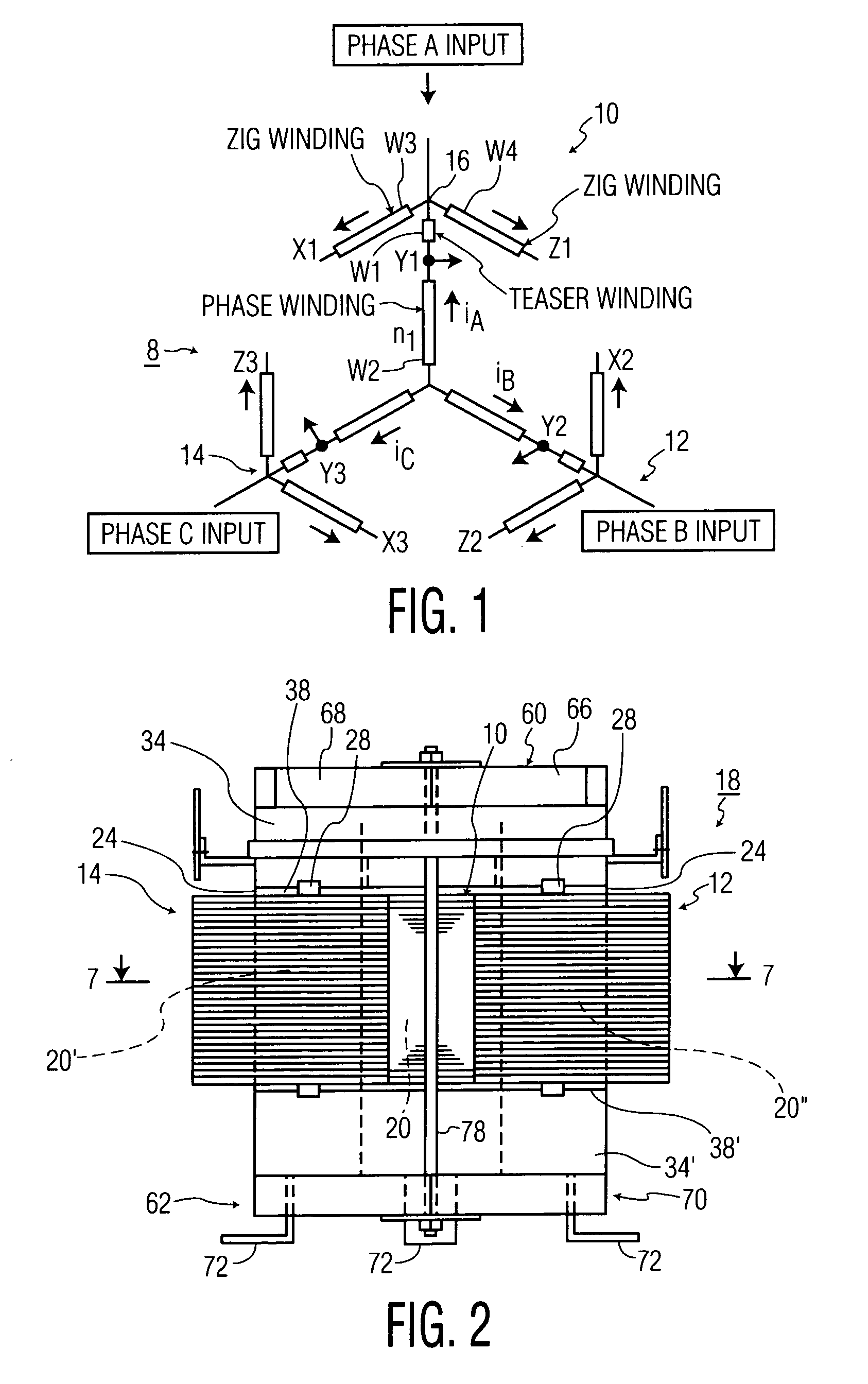
[0037] In FIG. 1, a phasor diagram 8 shows representative windings of a three phase fork AC / DC transformer. This diagram is identical to a diagram in the Paice patent mentioned in the introductory portion except this diagram has no delta winding as in the Paice diagram. In this diagram, the length of the rectangles representing windings represent the approximate relative length of the windings. The windings are arranged into three phases A, B and C at corresponding three legs 10, 12 and 14 of the physical construction of the transformer. The windings of each phase is identical to the windings of each of the other phases and a description of phase A is representative of the other phases. Phase A has a power input terminal 16 at the junction of clockwise zig winding w4 and counterclockwise zig winding w3 (referred to as a teaser winding in Paice). The terms “clockwise” and “counterclockwise” refer to the relative clock positions of the windings about the center of the diagram. A centr...


PUM

PropertyMeasurementUnit
thicknessaaaaaaaaaa
magnetic fluxaaaaaaaaaa
electricallyaaaaaaaaaa

Abstract

A fork autotransformer has a symmetrically arranged annular array of legs manifesting each phase of a three phase transformer. Each leg has a core about which three layers of windings are wound. The inner and outer windings are zig windings and the middle layer is a winding having one end connected to a junction of the zig windings as a power input and the other end connected to an end of the same winding of the other phases at a neutral point. Top and bottom yokes are magnetically coupled to, but are in electrical conductive isolation to, the cores. A Y-shaped clamp assembly clamps the yokes to the cores. The yokes are spaced from the cores to minimize even harmonic distortion using an insulating layer between the yokes and cores. No delta winding is needed as triplin harmonic flux is coupled from the cores to the yokes and circulates harmlessly in the yokes minimizing triplin harmonic distortion at the input lines while the insulation spacer between the yokes and cores minimizes even harmonics eliminating the need for input line reactors. The windings are wound in layers about the cores with spacers forming air cooling ducts with each other and the respective cores.

Description

[0001] This application claims the benefit of provisional application Ser. No. 60 / 584,683 filed Jul. 1, 2004 and incorporated in its entirety herein.BACKGROUND OF THE INVENTION [0002] This invention relates to phase shifting fork transformers, sometimes referred to as AC / DC converters, and more particularly, to a fork transformer with minimum third harmonic and multiples thereof distortion at its outputs. [0003] U.S. Pat. No. 5,455,759 to Paice, incorporated in its entirety by reference herein, discloses a symmetrical phase-shifting, fork transformer. However, this patent does not disclose or teach one of ordinary skill the details of the mechanical structure of the associated transformer used with the disclosed windings. The patent discloses what is referred to as a zig winding connected to a referred to teaser winding (which in the alternative may also be referred to as a zig winding) at a junction forming a power input terminal. A long winding has one end coupled to the junction ...

Claims


Application Information

Patent Timeline
Patent Type & Authority Applications(United States)
IPC IPC(8): H01F30/12
CPCH01F30/12H01F27/306
Inventor MAZUR, ALEXANDERWILUS, JOHN
Owner MAZUR ALEXANDER
Why Eureka
Try Eureka