Antenna, tag communication apparatus, tag communication system, scanning adjusting method for tag communication apparatus and computer readable medium

a communication system and tag technology, applied in direction finders using radio waves, instruments, reradiation, etc., can solve the problems of difficult to construct a system in which a number of rfid tags are required, and a lot of time and labor, so as to achieve effective expansion of communication area, wide communication area, and high directivity

Active Publication Date: 2006-01-05
ORMON CORP
View PDF15 Cites 41 Cited by
  • Summary
  • Abstract
  • Description
  • Claims
  • Application Information

AI Technical Summary

Benefits of technology

[0046] As described above, in the antenna for tag communication according to the present invention, the beam scanning antenna is employed that can perform the scanning with the beam of the transmitted radio wave. Thus, the communication area can be effectively enlarged compared with the general antenna having high directivity, and the wide communication area can be covered with the small number of antennas. Further, the scanning is performed with the beam so that the plane specified by the scanning direction of the beam intersects with the reflecting surface on which the strongest reflected wave is generated. Thus, the advancing direction of the beam is changed to the reflecting surface by the scanning. Accordingly, in the incommunicable region, the intensity of the radio wave of the direct wave differs from the intensity of the radio wave of the reflected wave from the reflecting surface so that the multipath interference is suppressed, the tag communication apparatus can communicate with the RFID tag and the wide communication area having no incommunicable region can be effectively covered.

Problems solved by technology

However, when the communication area is enlarged, following problems arise.
Thus, it is difficult to construct a system in which a number of RFID tags can be read and written simultaneously with a small number of antennas.
Further, when the antenna having low directivity is employed, a incommunicable region in which the tag communication apparatus cannot communicate with the RFID tag is generated in the communication area due to what is called a multipath interference, in which direct waves from the tag communication apparatus and reflected waves from a floor surface or a wall surface interfere with each other.
In this case, the RFID tag that cannot communicate with the tag communication apparatus may possibly be generated in the communication area, which is undesirable.
Further, there is a high possibility that a communicable region in which the tag communication apparatus can communicate with the RFID tag is generated outside the communication area due to the multipath interference.
However, since this adjustment needs to be carried out while confirming that the communication can be performed in each part inside the communication area, a lot of time and labor are required.

Method used


Image

  • Antenna, tag communication apparatus, tag communication system, scanning adjusting method for tag communication apparatus and computer readable medium
  • Antenna, tag communication apparatus, tag communication system, scanning adjusting method for tag communication apparatus and computer readable medium
  • Antenna, tag communication apparatus, tag communication system, scanning adjusting method for tag communication apparatus and computer readable medium

Examples


Embodiment Construction

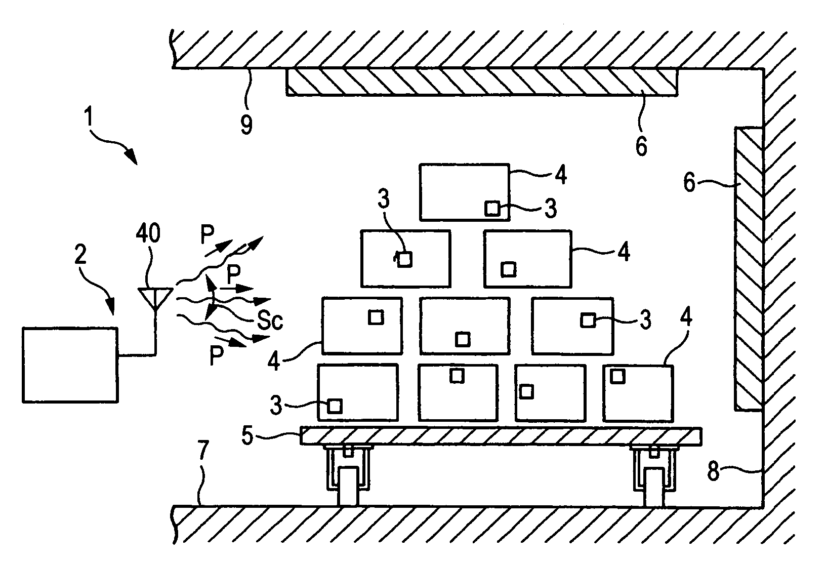
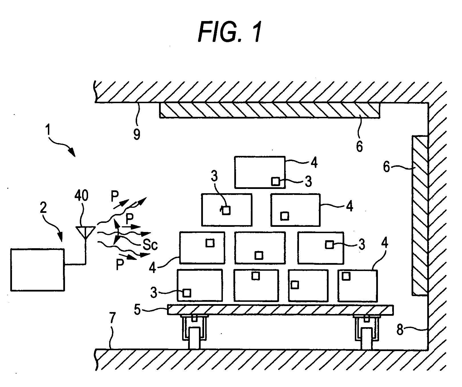
[0071] Now, an embodiment of the present invention will be described referring to FIGS. 1 to 11. FIG. 1 shows an outline of an RFID system (a tag communication system) of an embodiment. The RFID system 1 serves to identify goods contactless and automatically such as luggage for flight in an airport, cargoes in a physical distribution, works (intermediate goods) during a production process. Specifically, the RFID system 1 is a system in which an RFID reader / writer (hereinafter, referred to just as a reader / writer) 2 performs a radio communication with RFID tags 3 respectively attached to a number of goods 4 that are conveyed by a conveying device 5 such as an automatic transporter and a belt conveyor.

[0072] In this embodiment, a frequency band of a radio wave transmitted by the reader / writer (a tag communication apparatus) 2 is what is called a UHF band of approximately from 800 MHz to 960 MHz. Thus, an area in which the reader / writer 2 can communicate with the RFID tags 3 is around...


PUM


Abstract

An RFID reader/writer performs a radio communication with an RFID tag. An antenna for tag communication used in the RFID reader/writer is a beam scanning antenna that can perform scanning with the beam of a transmitted radio wave. The beam has a high directivity in a certain scanning direction. The scanning with the beam is performed so that a plane including the certain scanning direction intersects with a floor surface as a reflecting surface on which the strongest reflected wave is generated.

Description

[0001] This application claims foreign priority based on Japanese Patent application No. 2004-195979, filed Jul. 1, 2004, the contents of which is incorporated herein by reference in its entirety. BACKGROUND OF THE INVENTION [0002] 1. Field of the Invention [0003] The present invention relates to an apparatus for communicating with an RFID (Radio Frequency Identification) tag through a radio wave (hereinafter, referred to as tag communication apparatus), an antenna used for the tag communication apparatus, a tag communication system, a scanning adjusting method for tag communication apparatus and a computer readable medium for scanning adjustment. [0004] 2. Description of the Related Art [0005] In recent years, technology for RFID (Radio Frequency Identification) in which a tag communication apparatus as a reader and / or writer performs a radio communication with an RFID (Radio Frequency Identification) tag (radio tag) has been progressively employed. Further, the RFID tag is anticip...

Claims


Application Information

Patent Timeline
Patent Type & Authority Applications(United States)
IPC IPC(8): H01Q19/06G08B13/14
CPCG01S3/14G01S3/46G01S7/40H01Q3/30G06K7/10346H01Q3/26G01S13/75G06K17/00
Inventor SAITO, KEISUKEOKAMURA, SHINICHIROKAWAI, TAKEHIRO
Owner ORMON CORP
Why Eureka
Try Eureka