Network device with VLAN topology discovery functions

a network device and topology discovery technology, applied in the field of network devices, can solve the problems of inability to offer the capability of vlan topology discovery per se, and the unfulfilled demand for devices

Inactive Publication Date: 2006-01-05
FUJITSU LTD
View PDF3 Cites 130 Cited by
  • Summary
  • Abstract
  • Description
  • Claims
  • Application Information

AI Technical Summary

Problems solved by technology

The existing management tools such as those proposed in the aforementioned publications are unable to offer the capability of VLAN topology dis

Method used


Image

  • Network device with VLAN topology discovery functions
  • Network device with VLAN topology discovery functions
  • Network device with VLAN topology discovery functions

Examples


first embodiment

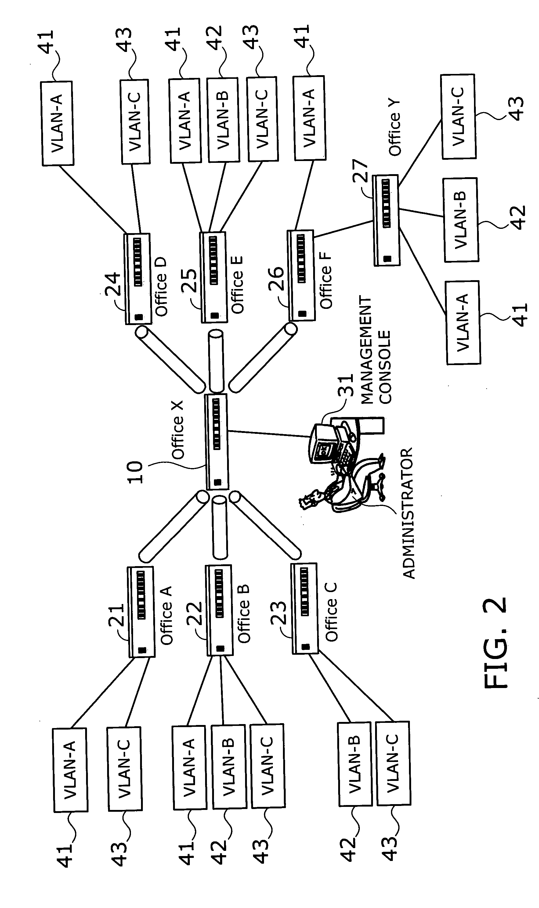
[0056] This section describes a network device according to a first embodiment of the present invention. FIG. 3 is a functional block diagram of a network device 10 according to a first embodiment. As seen from the diagram, the network device 10 contains a basic function block 11, a topology data interface 12, a topology analyzer 13, and a topology packet generator 14. Note that other network devices 21 to 27 in FIG. 2 have the same functional blocks as those of the network device 10 depicted in FIG. 3.

[0057] The basic function block 11 offers various fundamental facilities for transmitting and receiving packets to / from peer network devices. Specifically, the basic function block 11 contains a packet interface 11a, a packet parser 11b, a virtual network database 11c, a MAC address learning table 11d, and a command processor 11e. Those elements have the functions described as follows:

[0058] The packet interface 11a serves to transmit and receive packets to / from other network device...

second embodiment

[0123] Referring now to FIG. 27 and subsequent diagrams, this section describes a second embodiment of the present invention. The second embodiment is directed to a network system having a physical loop in the topology. Network devices in such a system have to control the paths of packets in order to prevent packets from flooding due to a loop. The second embodiment offers a function to discover packet delivery routes in a VLAN environment with a physical loop.

[0124]FIG. 27 shows an example system involving network devices according to the second embodiment of the present invention. The illustrated network involves six network devices 120 and 131 to 135, which are layer-2 switches that provide switched paths for delivering packets according to the layer-2 specifications of the ISO reference model. Attached to the left-most network device 120 is a management console 141 for use by a network administrator. A remote terminal 142 (e.g., personal computer) is linked to the network devic...


PUM


Abstract

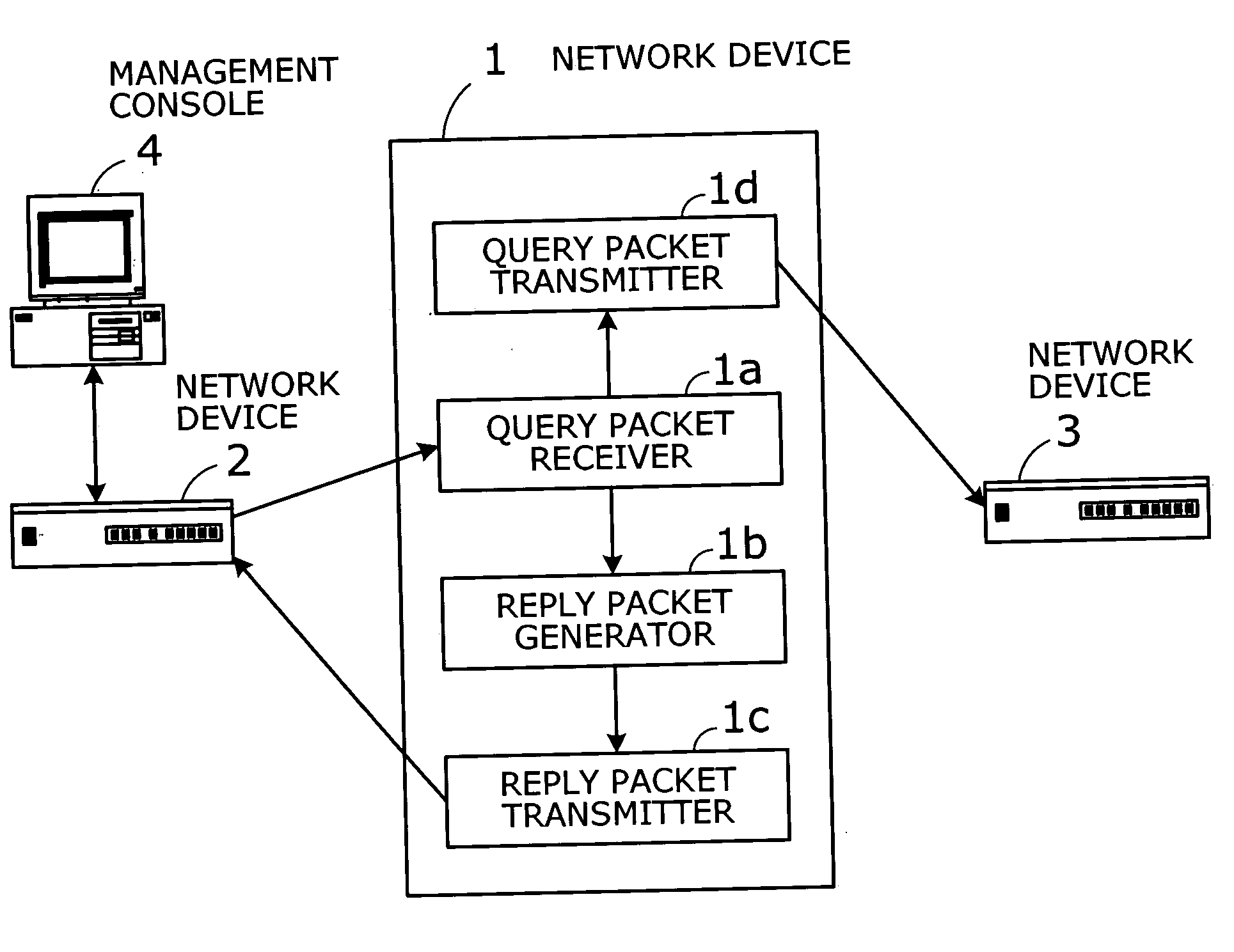
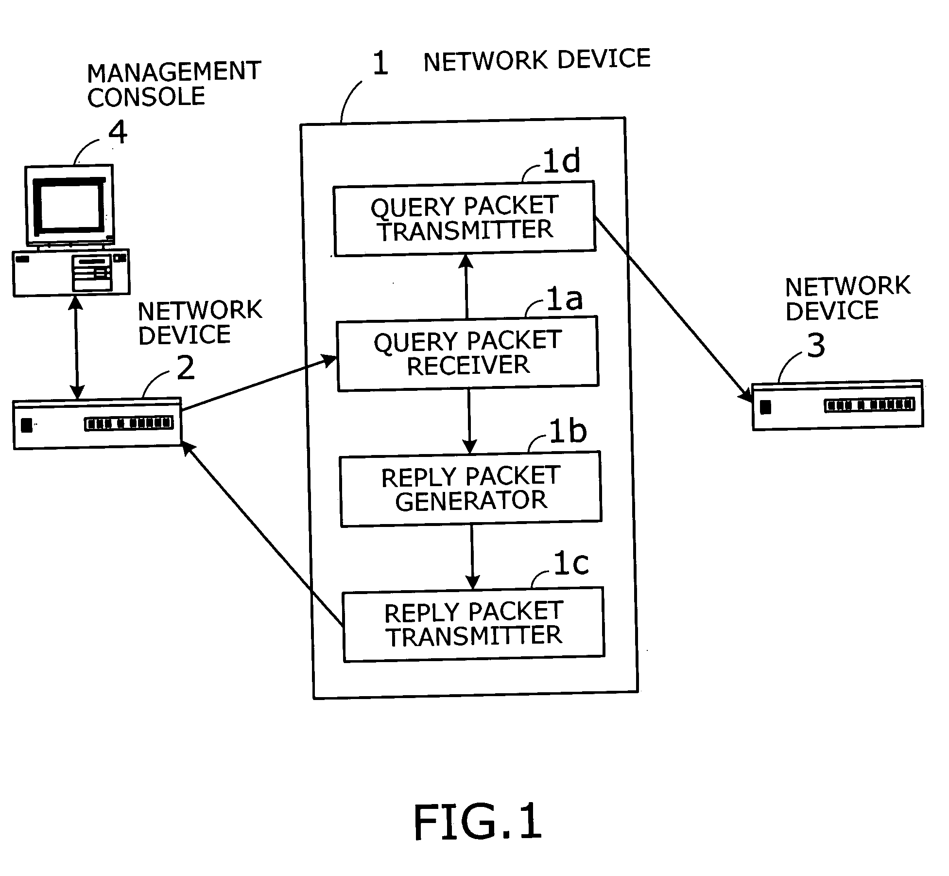
A network device with integrated topology discovery functions adapted to virtual local area networks (VLANs). VLAN segments are mapped on a network system formed from multiple network devices. One network device creates and broadcasts a query packet for topology discovery in each VLAN, in response to a command from a management console linked to that network device. At each receiving network device, a query packet receiver receives the query packet, and a reply packet is produced by a reply packet generator. A reply packet transmitter sends the produced reply packet back to the requesting network device. A query packet transmitter forwards the received query packet to neighboring subordinate network devices.

Description

CROSS-REFERENCE TO RELATED APPLICATIONS [0001] This application is based upon and claims the benefits of priority from the prior Japanese Patent Application No. 2004-193526, filed on Jun. 30, 2004, the entire contents of which are incorporated herein by reference. BACKGROUND OF THE INVENTION [0002] 1. Field of the Invention [0003] The present invention relates to network devices, and more particularly to a network device for building virtual networks. [0004] 2. Description of the Related Art [0005] In network management, system administrators need to understand how the network is laid out. To identify the topology of a network, they use Packet Internet Grouper (ping) commands from a terminal console (e.g., personal computer) attached to the network. A ping command verifies end-to-end connectivity to a specified destination. [0006] Topology discovery can also be achieved by using a dedicated network monitoring tool or a computer with equivalent software functions. Examples are seen i...

Claims


Application Information

Patent Timeline
IPC IPC(8): H04L12/28H04L12/46
CPCH04L12/4675H04L45/02H04L41/22H04L41/12H04L41/122
Inventor IWANAGA, TSUKASANAKASHIMA, KAZUHIROSAKATA, KOUJI
Owner FUJITSU LTD
Why Eureka
Try Eureka