Dynamic microphone

Inactive Publication Date: 2006-01-05
AUDIO-TECHNICA
View PDF4 Cites 4 Cited by
  • Summary
  • Abstract
  • Description
  • Claims
  • Application Information

AI Technical Summary

Benefits of technology

[0012] With this configuration, the lead end of the lead of the voice coil is elastically held through the elastic layer provided on the inner surface of the sub dome. Thus, even when the diaphragm is strongly pressed to the magnetism generating circuit, the cushion effect of the elastic layer can positively prevent a break.
[0013] Moreover, the elastic layer is formed, including the lead end of the lead, over the inner surface of the sub dome adjacent to the voice coil, thereby

Problems solved by technology

Dynamic microphones for base drums pick up heavy bass, and thus in general designs, diaphragms have low stiffness (soft diaphragms) and voice coils are he

Method used


Image

  • Dynamic microphone
  • Dynamic microphone
  • Dynamic microphone

Examples


Example

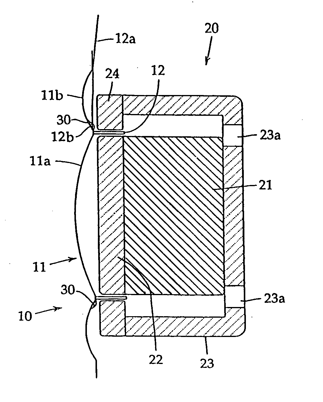
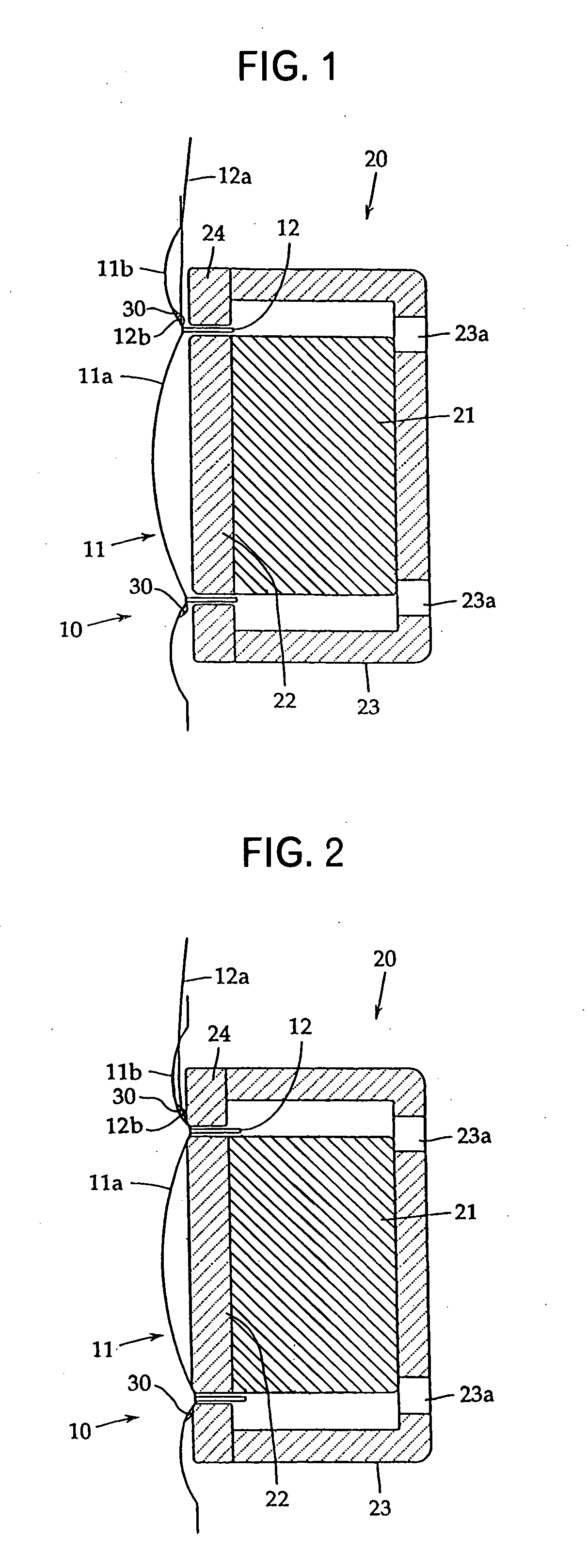
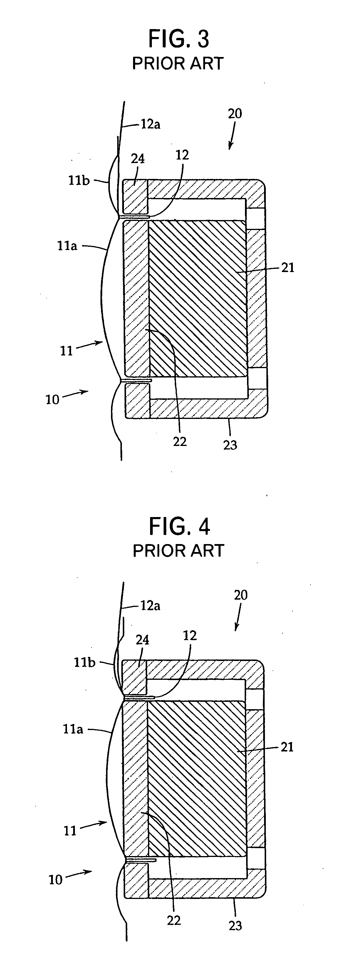
[0019] Referring to FIGS. 1 and 2, an embodiment of the present invention will be discussed below. The present invention is not limited to this embodiment. FIG. 1 is a sectional view showing a main part of a dynamic microphone according to the present invention. FIG. 1 corresponds to FIG. 3, and constituent elements not to be changed from those of the conventional example are indicated by the same reference numerals. FIG. 2 is a sectional view which shows the maximum displacement of a diaphragm in a similar manner to FIG. 4.

[0020] As shown in FIG. 1, the dynamic microphone comprises, as a basic configuration, a vibration part 10 vibrating with sound waves and a magnetism generating circuit 20. The vibration part 10 includes a diaphragm 11 and a voice coil 12.

[0021] The diaphragm 11 has a center dome 11a and a sub dome 11b coaxially provided around the center dome 11a. The center dome 11a and the sub dome 11b are integrally formed of an extremely thin (e.g., about 9μm) synthetic re...


PUM


Abstract

There is provided a dynamic microphone which prevents, with a simple configuration, the lead of a voice coil from breaking even when a strong sound pressure or the like presses a diaphragm to a magnetism generating circuit. The dynamic microphone includes a diaphragm 11 having a voice coil 12 attached to a boundary between a center dome 11a and a sub dome 11b, and a magnetism generating circuit 20 which has a pole piece 22 provided on one pole of a permanent magnet 21, a ring yoke 24 provided on the other pole of the permanent magnet 21, and a magnetic gap formed between the pole piece 22 and the ring yoke 24, the voice coil 12 being supported in the magnetic gap so as to vibrate through the diaphragm 11, the voice coil 12 having a lead 12a wired along the inner surface of the sub dome 11b, wherein the lead 12a of the voice coil 12 is elastically held on the sub dome 11b at least through an elastic layer 30 applied to the inner surface of the sub dome 11b adjacent to the voice coil 12.

Description

TECHNICAL FIELD [0001] The present invention relates to a dynamic microphone and more specifically relates to a dynamic microphone which makes it possible to effectively prevent the lead of a voice coil from breaking when a diaphragm undergoes an excessive displacement. BACKGROUND ART [0002]FIG. 3 is a sectional view showing a main part of an example of a conventional dynamic microphone. The basic configuration of the microphone comprises a vibration part 10 vibrating with sound waves and a magnetism generating circuit 20. The vibration part 10 comprises a diaphragm 11 and a voice coil (generator coil) 12. In this case, the diaphragm 11 has a center dome 11a and a sub dome 11b provided around the center dome 11a. The voice coil 12 is joined to a boundary between the center dome 11a and the sub dome 11b with an adhesive. [0003] The magnetism generating circuit 20 comprises a permanent magnet 21, a pole piece 22 provided on one pole of the permanent magnet 21, and a ring yoke 24 magne...

Claims


Application Information

Patent Timeline
IPC IPC(8): H04R1/00
CPCH04R9/08
Inventor AKINO, HIROSHI
Owner AUDIO-TECHNICA
Why Eureka
Try Eureka