Security document and verification method

a security document and verification method technology, applied in the field of security documents and verification methods, can solve the problems of difficult manufacturing of oblique perforations and the likelihood of degradation of quality, and achieve the effect of increasing the reliability of verification

Inactive Publication Date: 2006-01-12
ORELL FJUSSLI ZIKHERKHAJTSDRUK AG
View PDF17 Cites 27 Cited by
  • Summary
  • Abstract
  • Description
  • Claims
  • Application Information

AI Technical Summary

Benefits of technology

The invention relates to documents that have multiple small holes (perforations) with different shapes. By looking at these holes from one perspective, it becomes easier to see them all without confusion. This improves the accuracy of identifying important features on the document. To achieve optimal results, the smallest hole needs to be about the same size as the material used for the container the document is placed in.

Problems solved by technology

The technical problem addressed in this patent is to increase the uniqueness of fine perforations used as a security feature for security documents, in order to provide a higher degree of recognizability and reliability. Current methods of adding perforations that are visible in transmission and invisible in reflection have limitations in terms of their manufacturing quality and durability over time, especially for paper or thin plastic sheet documents that are subjected to frequent mechanical stress.

Method used


Image

  • Security document and verification method
  • Security document and verification method
  • Security document and verification method

Examples


Embodiment Construction

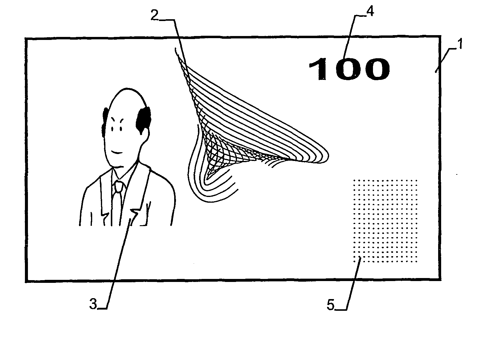
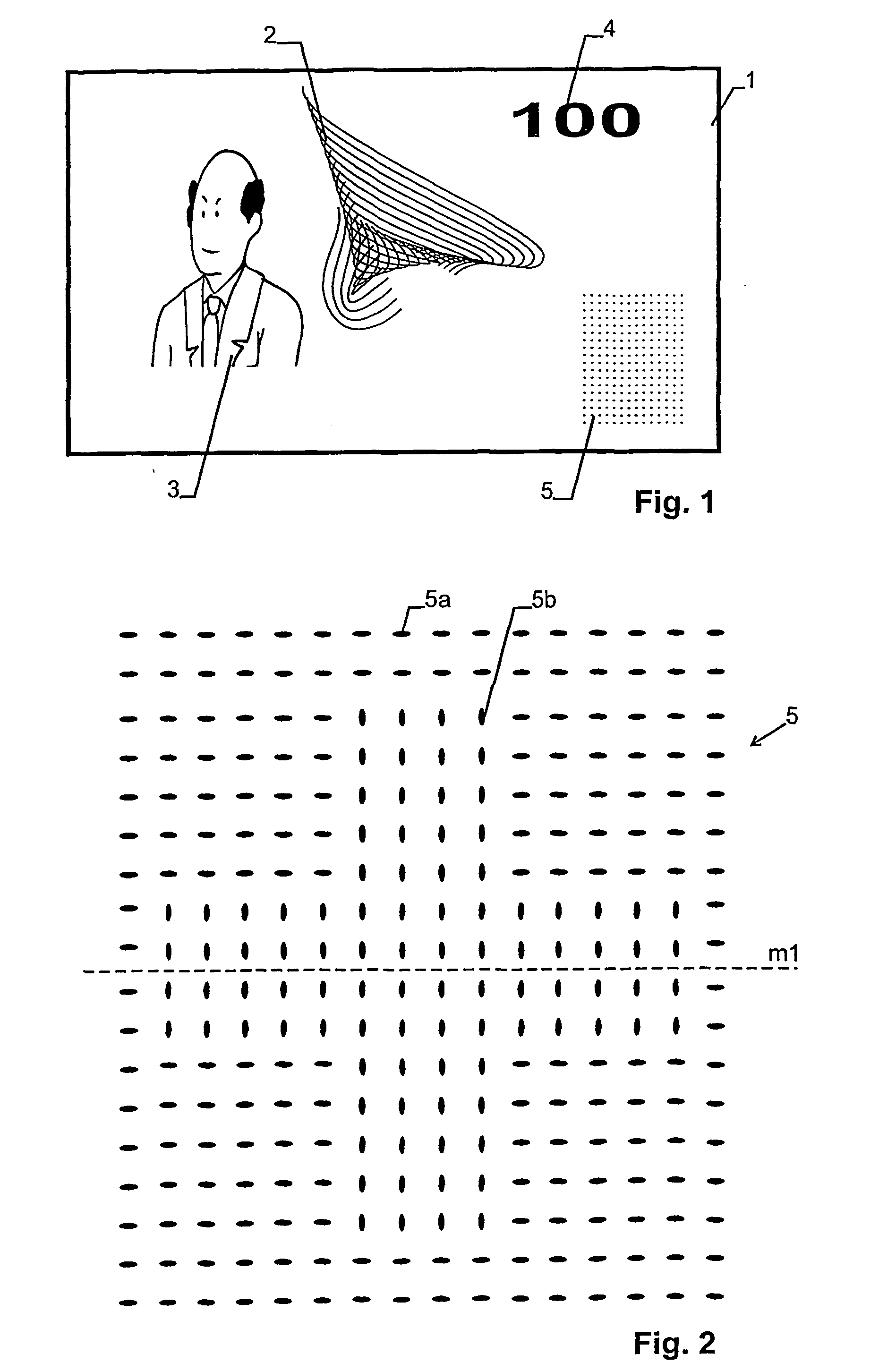
[0018]FIG. 1 shows a bank note having a carrier 1 of paper or plastic with conventional graphical and textual elements 2, 3, 4 and a security perforation pattern 5.

[0019] As shown in FIG. 2, security perforation pattern 5 comprises a plurality of perforations (holes) 5a, 5b extending through carrier 1. The perforations are arranged in a two-dimensional array. Preferably, they extend through the whole of carrier 1, but they may also extend only partially therethrough as long as the optical transmission when viewed from a viewing direction perpendicular to the surface of carrier 1 is much larger at a perforation than at unperforated locations.

[0020] As can be seen from FIG. 2, which is a close-up of perforation pattern 5, two different types of holes are used.

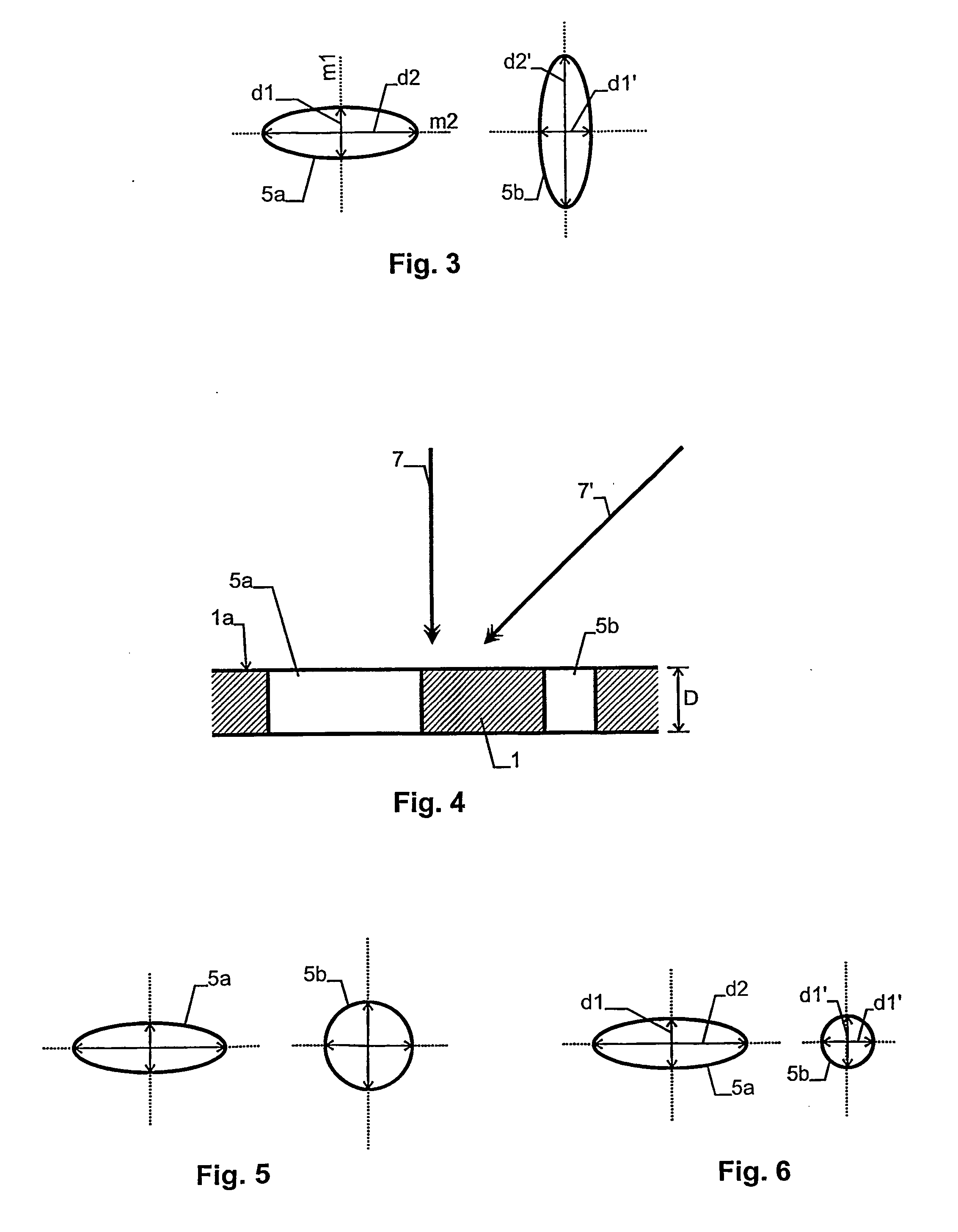
[0021] A hole 5a and 5b, respectively, of each perforation type is shown in FIG. 3. In the shown embodiment, each hole 5a, 5b has elongate cross section and extends through carrier 1 in a direction perpendicular to the surface...


PUM


Abstract

A security document, such as a banknote or a cheque, is provided with a perforation pattern (5) having holes (5a, 5b) with elongate cross section. When viewing the perforation pattern (5) from a direction that is non-perpendicular to the surface of the document, different holes will have different optical transmission, which can be verified by eye or electronically. Perforation patterns (5) of this type are hard to forge and easy to verify.

Description


Claims


Application Information

Patent Timeline
Owner ORELL FJUSSLI ZIKHERKHAJTSDRUK AG
Why Eureka
Try Eureka