Method and apparatus for high resolution 3D imaging

a high-resolution, 3d imaging technology, applied in navigation instruments, instruments, instruments for comonautical navigation, etc., can solve the problems of high cost of scanning systems, complex mechanics of scanners, and inability to accurately detect objects

Active Publication Date: 2006-01-12
TOPCON POSITIONING SYST INC
View PDF33 Cites 115 Cited by
  • Summary
  • Abstract
  • Description
  • Claims
  • Application Information

AI Technical Summary

Problems solved by technology

However, adapting such systems to image remote objects challenges the sensitivity and speed of available devices.
Scanning systems tend to be expensive.
The mechanics of the scanner are complex.
They also increase the weight of the system and reduce reliability.
Scannerless systems, on the other hand, have difficulty building an accurate three-dimensional scene from a series of discrete images.

Method used


Image

  • Method and apparatus for high resolution 3D imaging
  • Method and apparatus for high resolution 3D imaging
  • Method and apparatus for high resolution 3D imaging

Examples


Embodiment Construction

[0018] In the following detailed description of the preferred embodiments, reference is made to the accompanying drawings which form a part hereof, and in which is shown by way of illustration specific embodiments in which the invention may be practiced. It is to be understood that other embodiments may be utilized and structural changes may be made without departing from the scope of the present invention.

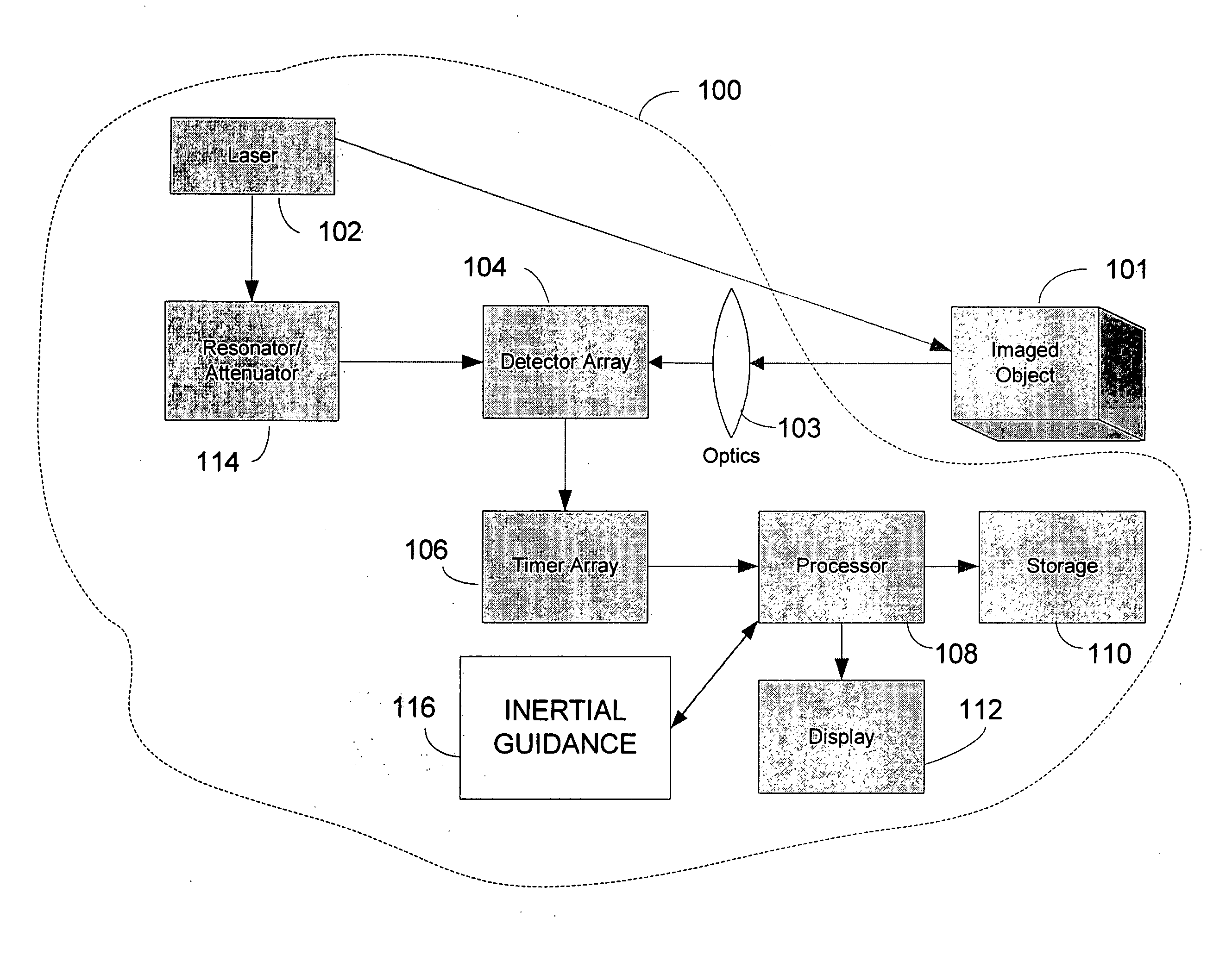
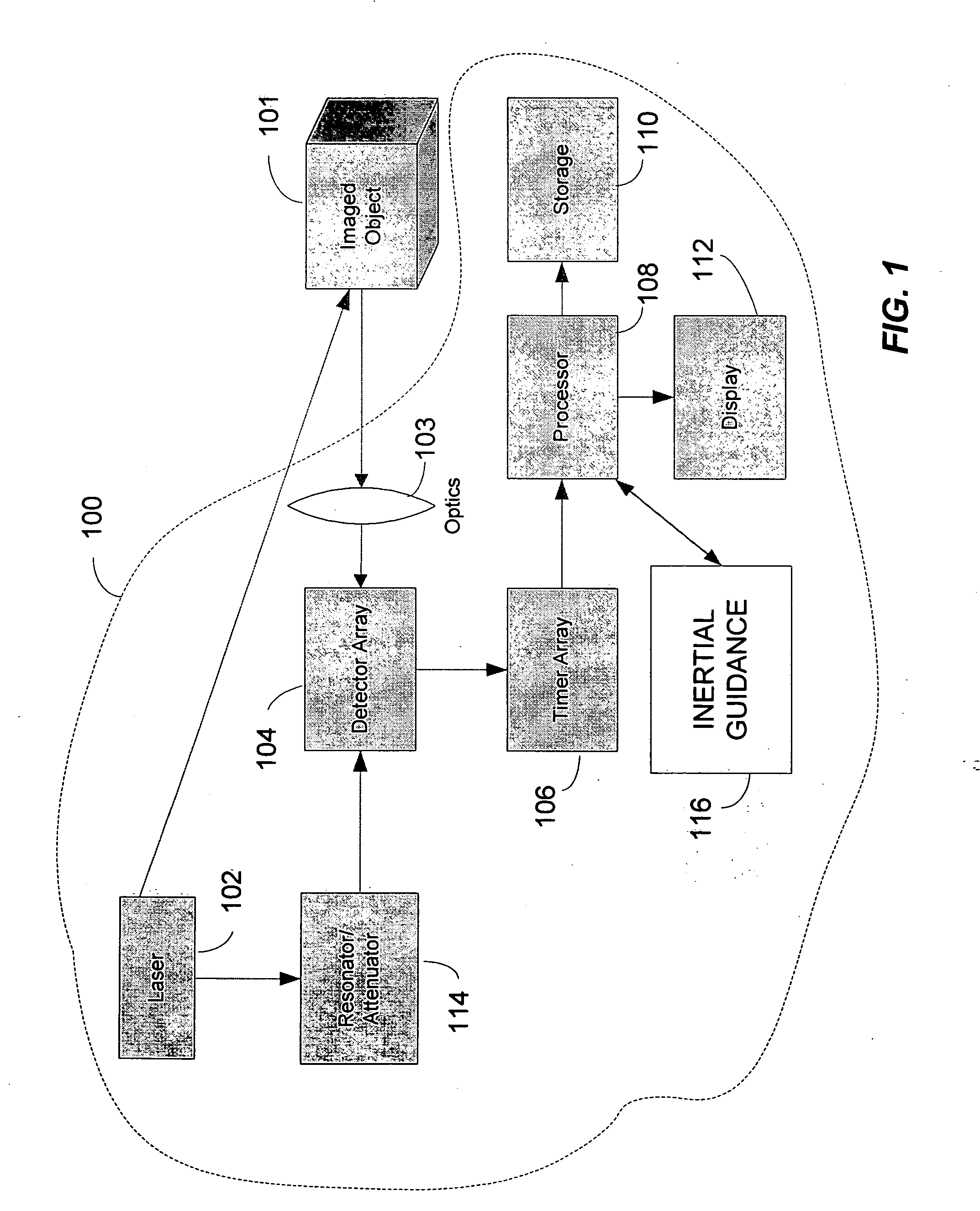
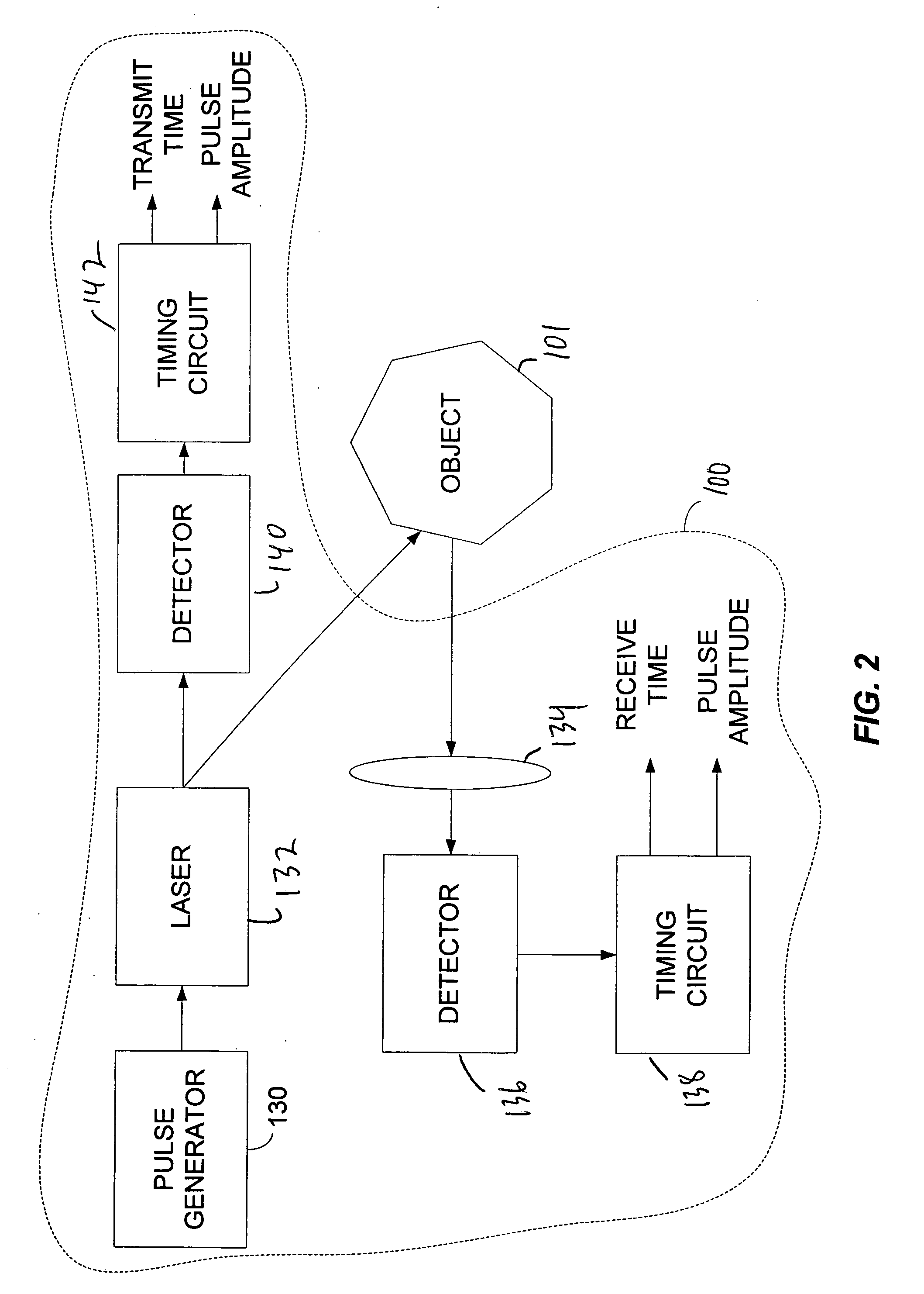
[0019] A representative system 100 for creating a high resolution three-dimensional image of a scene of interest 101 is shown in FIG. 1. A pulsed light source 102, typically a laser, is directed toward target scene 101. A portion of the light is reflected back from the scene. An array of detectors 104 receives the light from portions of the scene. The distance from the system to the portion of the scene 101 in the field of view of a single detector is determined by the time required for the light to illuminate that portion and then return to the detectors 104.

[0020] In the embod...


PUM


Abstract

A system and method for imaging a three-dimensional scene having one or more objects. The system includes a light source, a detector array, a timing circuit, an inertial guidance system and a processor connected to the timing circuit and the inertial guidance system. The light source generates an optical pulse and projects the optical pulse on an object so that it is reflected as a reflected pulse. The detector array includes a plurality of detectors, wherein the detectors are oriented to receive the reflected pulse. The timing circuit determines when the reflected pulse reached detectors on the detector array. The inertial guidance system measures angular velocity and acceleration. The processor forms a composite image of the three-dimensional scene as a function of camera position and range to objects in the three-dimensional scene.

Description

CROSS-REFERENCE TO RELATED APPLICATION [0001] This application is related to U.S. patent application Ser. No. ______, entitled “System and Method for Determining Range in 3D Imaging Systems”, Attorney Docket No. 1980.002US1, filed on even date herewith, which is incorporated herein by reference. BACKGROUND OF THE INVENTION [0002] 1. Field of the Invention [0003] This invention relates to imaging of objects by laser radar and more particularly to imaging based on an array of semiconductor detectors. [0004] 2. Background Information [0005] Laser techniques, such as LADAR (Laser Detection and Ranging) or “LIDAR” (Light Detection and Ranging), are used to image objects in three-dimensional image systems. Light, often from a laser source, is directed toward an object of interest. Reflected light from the object is then gathered and focused on one or more photodetectors. [0006] LADAR and LIDAR systems are capable of determining the distance to an object, for example, by timing the travel ...

Claims


Application Information

Patent Timeline
Patent Type & Authority Applications(United States)
IPC IPC(8): G01C21/02G01S17/89
CPCG01C11/06G01S17/89G01C21/16G01C15/002G01C21/1656G01C21/183
Inventor DIMSDALE, JERRYLEWIS, ANDREWCHEN, WILLIAM
Owner TOPCON POSITIONING SYST INC
Why Eureka
Try Eureka