Methods, systems, and data structures for generating a rasterizer

a rasterizer and data structure technology, applied in the field of rasterizer applications, can solve the problems of large variety of electronic devices which do not have sufficient storage or memory, cannot benefit from robust rasterizer applications, and devices with extremely limited graphics capabilities

Inactive Publication Date: 2006-01-12
INTEL CORP
View PDF2 Cites 12 Cited by
  • Summary
  • Abstract
  • Description
  • Claims
  • Application Information

AI Technical Summary

Problems solved by technology

However, this is a considerable waste of storage and memory on the device.
As a result, a large variety of electronic devices which do not have sufficient storage or memory cannot benefit from robust rasterizer applications.
Thus, conventionally these devices have extremely limited graphics capabilities.

Method used


Image

  • Methods, systems, and data structures for generating a rasterizer
  • Methods, systems, and data structures for generating a rasterizer
  • Methods, systems, and data structures for generating a rasterizer

Examples


Embodiment Construction

[0013] Novel methods, systems, and data structures for producing a rasterizer are taught. In the following detailed description of the embodiments, reference is made to the accompanying drawings, which form a part hereof, and in which is shown by way of illustration, but not limitation, specific embodiments of the invention that may be practiced. These embodiments are described in sufficient detail to enable one of ordinary skill in the art to understand and implement them, and it is to be understood that other embodiments may be utilized and that structural, logical, and electrical changes may be made without departing from the spirit and scope of the present disclosure. The following detailed description is, therefore, not to be taken in a limiting sense, and the scope of the embodiments of the inventions disclosed herein is defined only by the appended claims.

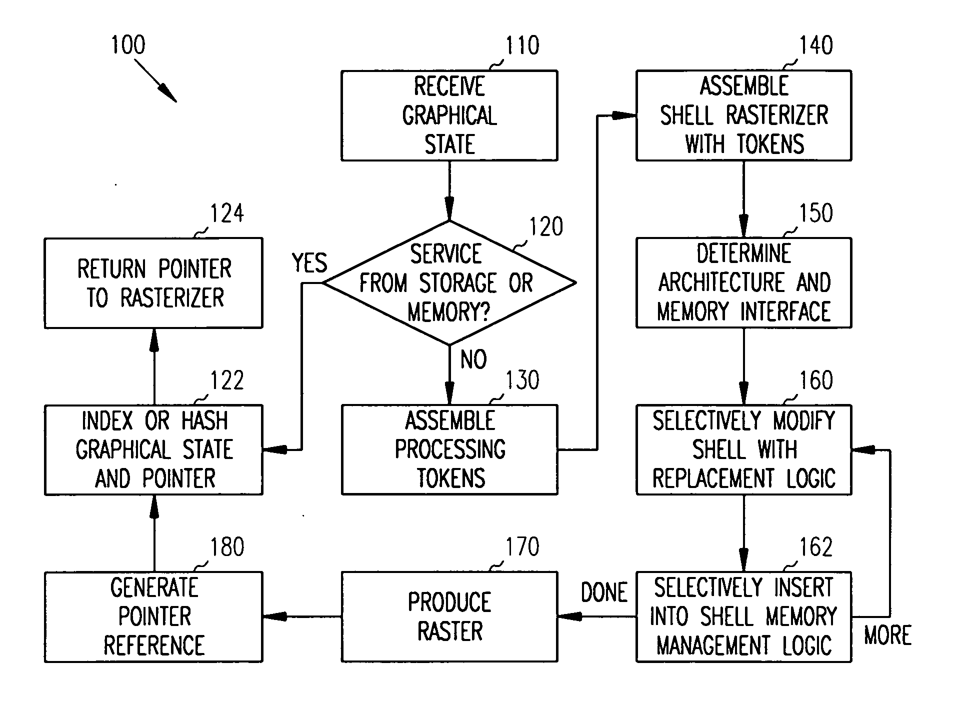
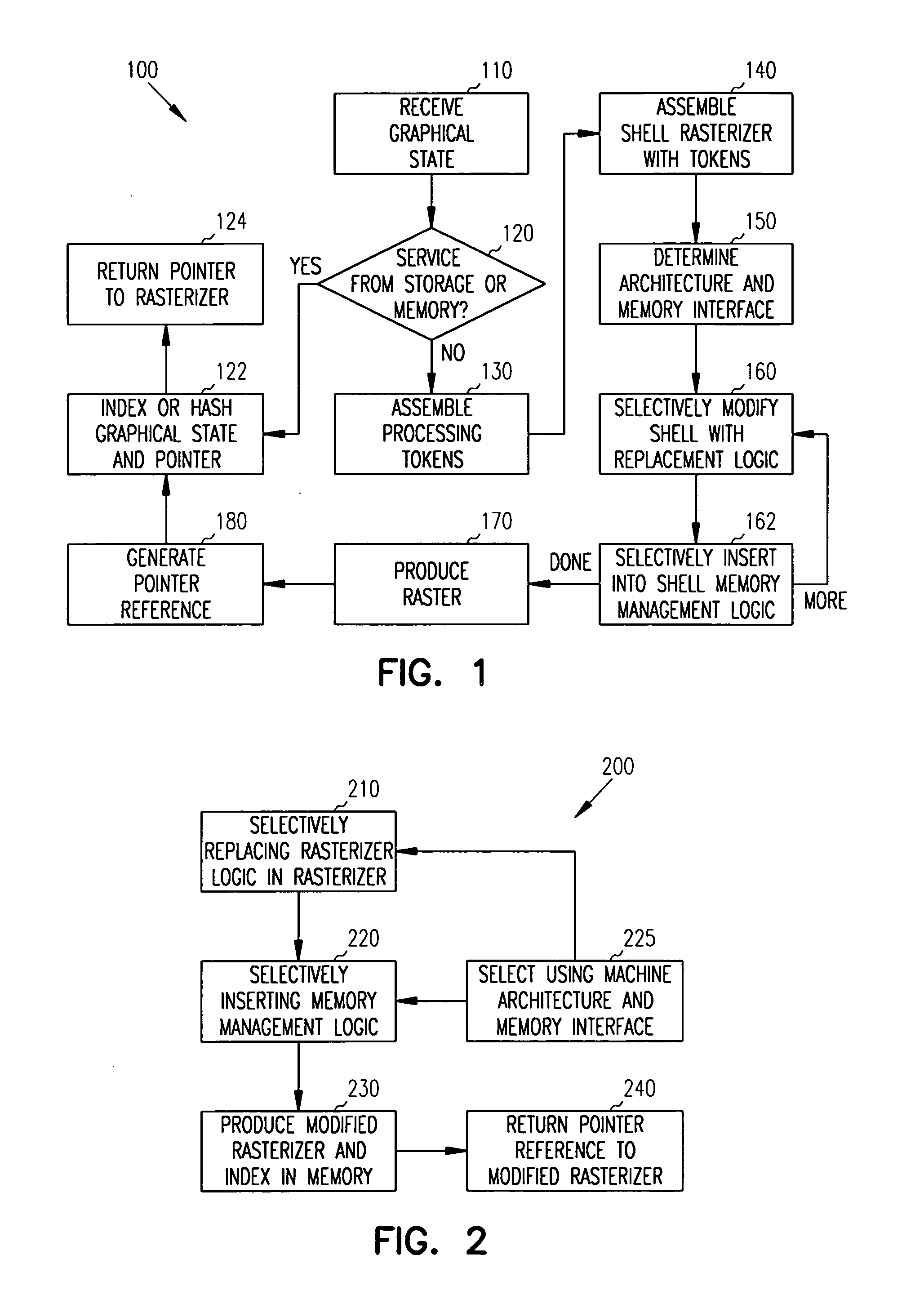
[0014]FIG. 1 illustrates a flow diagram of one method 100 for providing a rasterizer, in accordance with one embodiment o...


PUM


Abstract

Methods, systems and data structures produce a rasterizer. A graphical state is detected on a machine architecture. The graphical state is used for assembling a shell rasterizer. The machine architecture is used for selecting replacement logic that replaces portions of shell logic in the shell rasterizer. The machine architecture is used for selectively inserting memory management logic into portions of the shell logic to produce.

Description

[0001] This application is a continuation of U.S. patent application Ser. No. 10 / 608,453, filed on Jun. 26, 2003, which is incorporated herein by reference.TECHNICAL FIELD [0002] Embodiments of the present invention relate generally to rasterizer applications, and more particularly to dynamically generating a rasterizer application for a desired graphical state. BACKGROUND INFORMATION [0003] Three-dimensional images (3D) can be rendered on an electronic display using two steps. The first step is for transforming a desired graphical state to pixel coordinates. The second step is for drawing lines connecting the coordinates and for filling a geometric structure represented by the connected coordinates with pixel data (attributes). A graphical state is a desired image that is to be rendered on the electronic display. [0004] During the transformation step, two-dimensional (2D) space projected polygons are produced. Moreover, light source parameters are applied for producing vertex color...

Claims


Application Information

Patent Timeline
Patent Type & Authority Applications(United States)
IPC IPC(8): G06F15/00G06T15/00G06T17/00
CPCG06T15/005G06T1/20G06T1/00
Inventor HUX, WILLIAM A.JUNKINS, STEPHEN
Owner INTEL CORP
Why Eureka
Try Eureka