Electrical switch having an electrical connection element

a technology of electrical connections and switches, applied in the direction of coupling device connections, printed circuit aspects, contacts, etc., can solve the problems of inability to produce connection, inability to access or the like in the electrical switch for the purpose of producing the connection, and inability to achieve robust connection

Active Publication Date: 2006-01-12
MARQUARDT GMBH SCHLOSSTRASSE 16 7201 RIETHEIM-WEILHEIM 1 WEST GERMANY
View PDF6 Cites 9 Cited by
  • Summary
  • Abstract
  • Description
  • Claims
  • Application Information

AI Technical Summary

Benefits of technology

[0017] In addition to the improvements mentioned above, the advantages achieved by the present invention can especially be seen in that the electrical switch is composed of two separate units, namely the electronic control circuit and the contact system. These two units can be separately preassembled, and the connection element can be attached during the production of the control circuit in a conventional automated fitting machine and in the soldering unit. At the end of the assembly process, the two units are then joined by means of the connection element using a suitable high current connection technique to form the complete switch. The connection element according to the present invention can also be produced in a cost-effective and reliable manner.

Problems solved by technology

The production of such a robust connection requires considerable complexity in the manufacture of a suitable switch and presents problems when handling the switch during assembly.
Soldering is especially undesirable for providing the connection during the manufacture of the switch in view of the risk of impermissible heating of adjacent components in the control circuit and of soldering flux sprays.
Accessibility or the like in the electrical switch for the purpose of producing the connection is often also impaired.
This device has a significant disadvantage, however, associated with the complex and imprecise assembly of this connection element.

Method used


Image

  • Electrical switch having an electrical connection element
  • Electrical switch having an electrical connection element
  • Electrical switch having an electrical connection element

Examples


Embodiment Construction

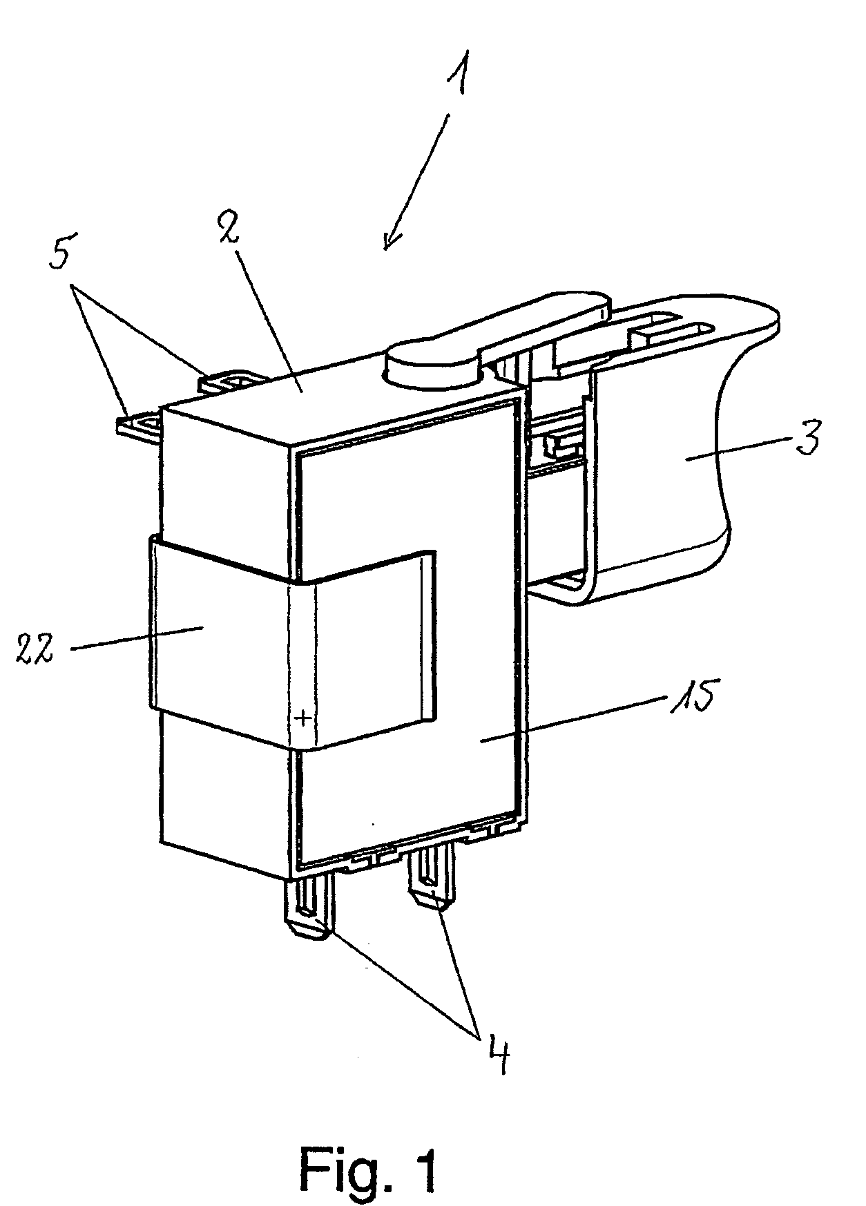
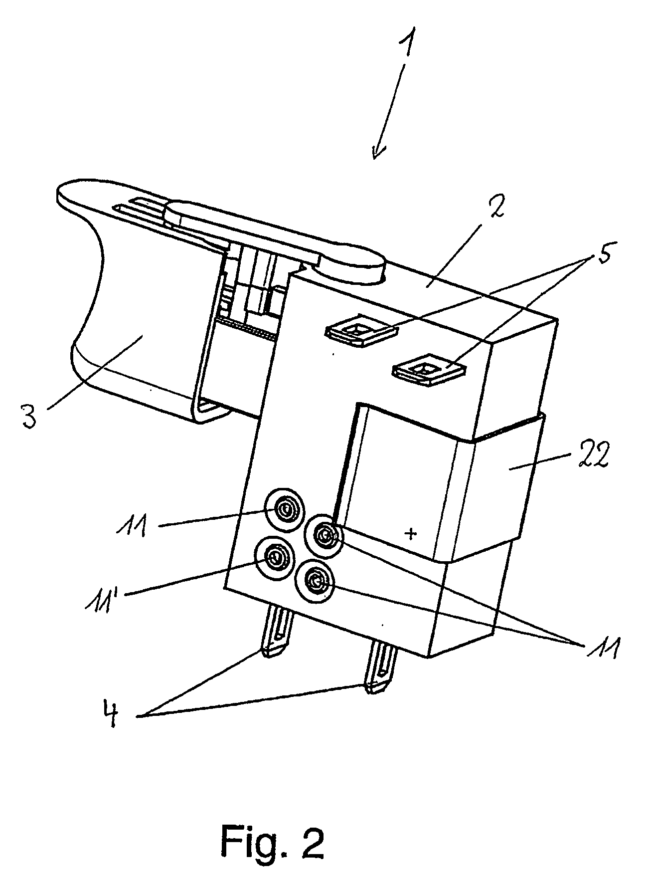
[0024]FIG. 1 shows an electrical switch 1 for a rechargeable electric tool which operates using a DC voltage. The switch 1 has a housing 2 on which there is arranged an actuating member 3 in the form of a pushbutton to be operated by the user. By moving the actuating member 3, the motor of the electric tool is switched on and its rotation speed is set corresponding to the position of the actuating member 3. The switch 1 has electrical input terminals 4 to which the electrical voltage of the rechargeable battery is connected and electrical output terminals 5 (visible in FIG. 2) to which the electrical voltage for operating the electric motor of the electric tool is applied.

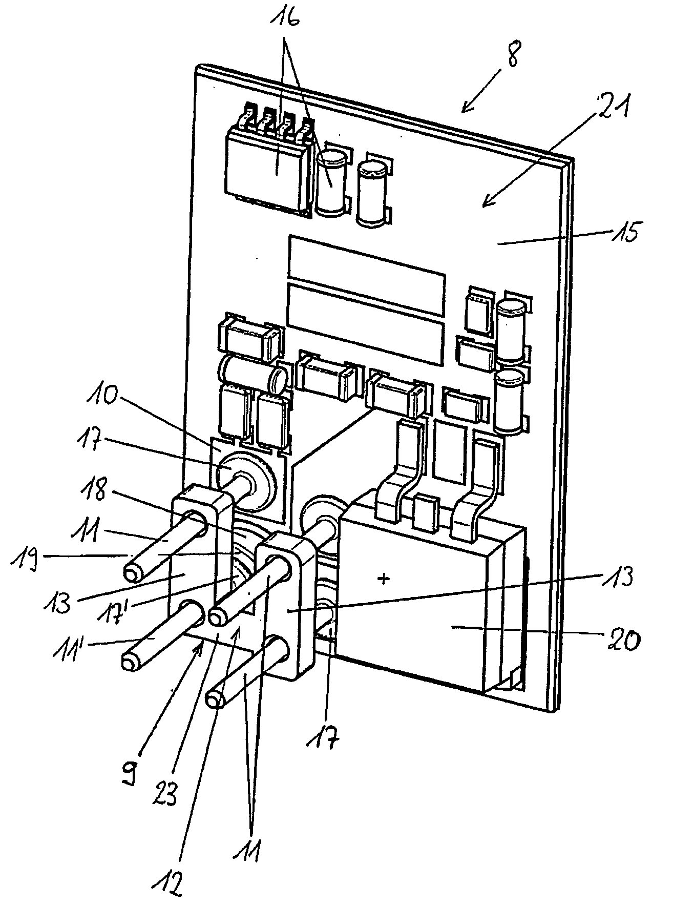
[0025] As can be seen in FIG. 4, the electrical voltage is carried from the input terminals 4, which are connected to the rechargeable battery, by means of power supply lines 6 into and within the interior of the housing 2. The electrical voltage for the purpose of operating the electric motor is in turn carried b...


PUM


Abstract

An electrical switch for an electric device is provided, including a contact system including at least one electrical power supply line, an electronic control circuit and an electrical connection element arranged between at least one contact face of the control circuit and the power supply line. The electrical connection element has at least one metal pin that is fixed in an electrically non-conductive fixing element such that the pin is aligned with respect to the contact face and the power supply line, and such that the pin protrudes from the fixing element on both sides thereof to contact the contact face and the power supply line.

Description

CROSS REFERENCE TO RELATED APPLICATIONS [0001] This application is a continuation of International Application No. PCT / EP2004 / 000445, having an international filing date of Jan. 21, 2004, which designated the United States, the entirety of which is incorporated herein by reference. This application also claims the benefit of German Application No. 103 02 305.4, filed Jan. 22, 2003, the entirety of which is incorporated herein by reference.FIELD OF THE INVENTION [0002] The present invention generally relates to an electrical switch having an electrical connection element, and in particular, to an electric tool switch having an electrical connection element. BACKGROUND OF THE INVENTION [0003] Electric tool switches, such as those disclosed in WO 02 / 078029 A1, for example, and such as those for a rechargeable electric tool, in addition to the associated contact system, often include an electronic control circuit for the purpose of driving the electric motor in the electric device. Elec...

Claims


Application Information

Patent Timeline
Patent Type & Authority Applications(United States)
IPC IPC(8): H01R12/00H01H9/06H05K3/30
CPCH01H9/06H01H2001/5888H05K2201/10424H05K3/303H05K2201/10318H01H2011/0087Y02P70/50
Inventor BROGHAMMER, PETERWAHL, PETER
Owner MARQUARDT GMBH SCHLOSSTRASSE 16 7201 RIETHEIM-WEILHEIM 1 WEST GERMANY
Why Eureka
Try Eureka