

Logical disk management method and apparatus
a logical disk and management method technology, applied in the direction of instruments, computing, electric digital data processing, etc., can solve the problems of inability to easily eliminate bottleneck inability to distinguish block addresses of logical disks and corresponding array configurations, and disadvantages of conventional disk array apparatuses
- Summary
- Abstract
- Description
- Claims
- Application Information
AI Technical Summary
Problems solved by technology
Method used
Image

Examples
first modification
[First Modification]
[0078] Next, a first modification of the above-described embodiment will be described with reference to FIG. 12. According to the above embodiment, the disk array apparatus 10 and the host 20 are connected directly. However, recently, a computer system, in which at least one disk array apparatus, for example, a plurality of disk array apparatuses and at least one host, for example, a plurality of hosts are connected with a network called storage area network (SAN), has appeared.
[0079]FIG. 12 shows an example of such a computer system. In FIG. 12, disk array apparatuses 10-0 and 10-1 and hosts 20-0 and 20-1 are connected with a network N like SAN. The hosts 20-0 and 20-1 share the disk array apparatuses 10-0 and 10-1 as their external storage units. However, the disk array apparatuses 10-0 and 10-1 are not recognized from the hosts 20-0 and 20-1. That is, the disk array apparatuses 10-0 and 10-1 are recognized as a logical disk achieved by using the storage area ...
second modification
[Second Modification]
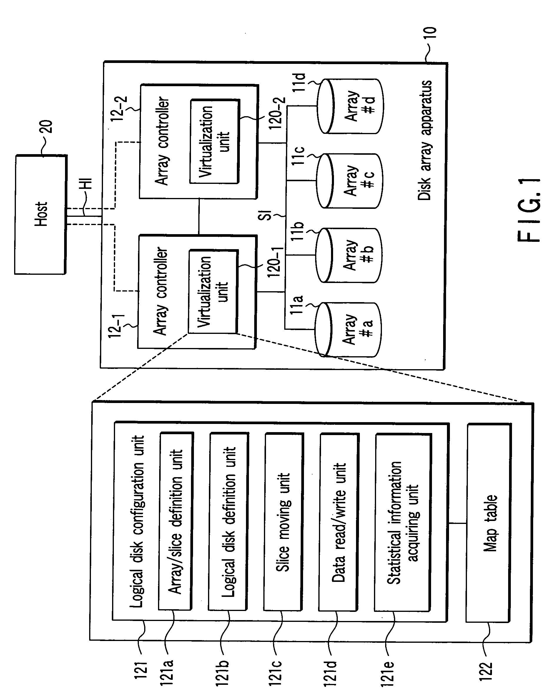
[0081] Next, a second modification of the above embodiment will be described with reference to FIG. 13. FIG. 13 is a block diagram showing a configuration of a computer system provided with the disk array apparatuses according to the second modification of the embodiment of the present invention. In FIG. 13, like reference numerals are attached to the same components as elements shown in FIG. 1. The computer system of FIG. 13 comprises a disk array apparatus 130 and the host 20. The disk array apparatus 130 is different from the disk array apparatus 10 shown in FIG. 1 in that it has a silicon disk device 131. The silicon disk device 131 is a storage device such as a battery backed-up type RAM disk device, which is constituted of plural memory devices such as dynamic RAMs (DRAMs). The silicon disk device 131 is so designed that the same access method (interface) as used for the HDD can be used to access the device 131 from the host. Because the silicon disk devic...
third modification
[Third Modification]
[0098] According to the above embodiment, the first modification and the second modification thereof, at a point of time when a logical disk is constructed, slices constituting the logical disk are assigned to an array. However, when a first access to slices in the logical disk is requested from the host to the disk array apparatus, those slices may be assigned within the storage area of the array.
[0099] According to the third modification, when a slice in the logical disk is used first, that is, the slice is changed from an unused slice to a used slice, an array constructing method for assigning the slices to the storage area of the array is applied. The array constructing method applied to the third modification will be described with reference to FIG. 17. The third modification is applied to the disk array apparatus 130 shown in FIG. 13 like the second modification.
[0100]FIG. 17 shows a logical disks 171 and an array 172 (#0). The logical disk 171 includes s...
PUM
 Abstract
Description
Claims
Application Information