Molding for drywall ceiling grid

a technology of drywall ceilings and grids, applied in the field of interior ceilings of drywall, can solve the problems of time and effort expended in accurately positioning beams, and achieve the effect of quick and accura

Active Publication Date: 2006-01-19
WORTHINGTON ARMSTRONG VENTURE
View PDF6 Cites 25 Cited by
  • Summary
  • Abstract
  • Description
  • Claims
  • Application Information

AI Technical Summary

Benefits of technology

[0012] The wall molding of the present invention provides a quick and accurate way of positioning, and securing, the end of a beam that has hems along flanges of the beam. Such beams are depicted in the '098 patent. The beams are positioned along, and secured to, the ledge of a wall molding having a right angle section, in a ceiling grid for a drywall suspended ceiling.

Problems solved by technology

In placing the ends of the beams on the wall molding ledge, much time and effort are expended in accurately positioning the beams along the ledge, and in securing the beam to the ledge.

Method used


Image

  • Molding for drywall ceiling grid
  • Molding for drywall ceiling grid
  • Molding for drywall ceiling grid

Examples


Embodiment Construction

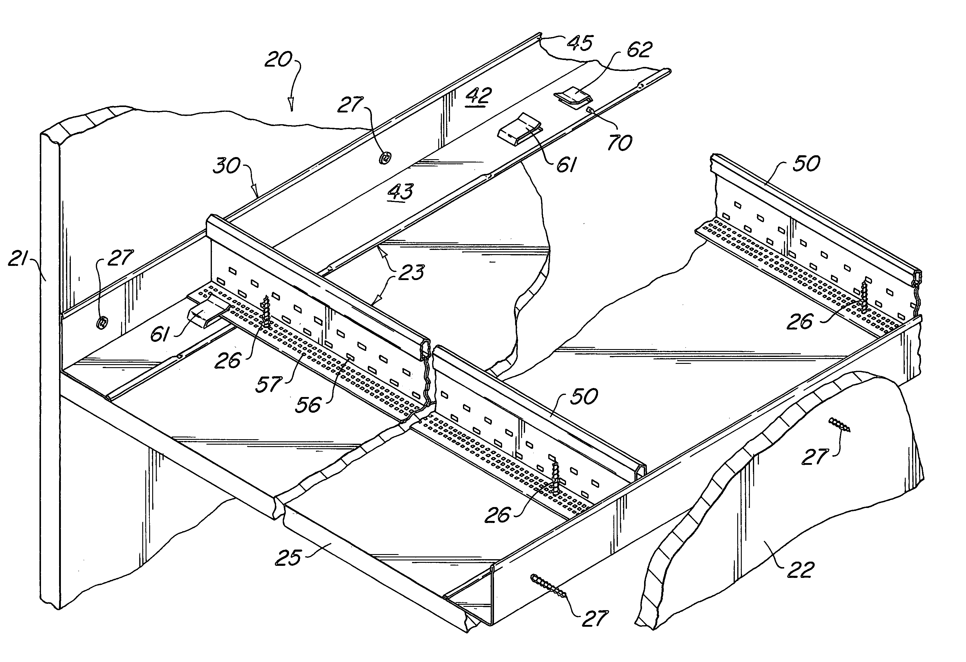
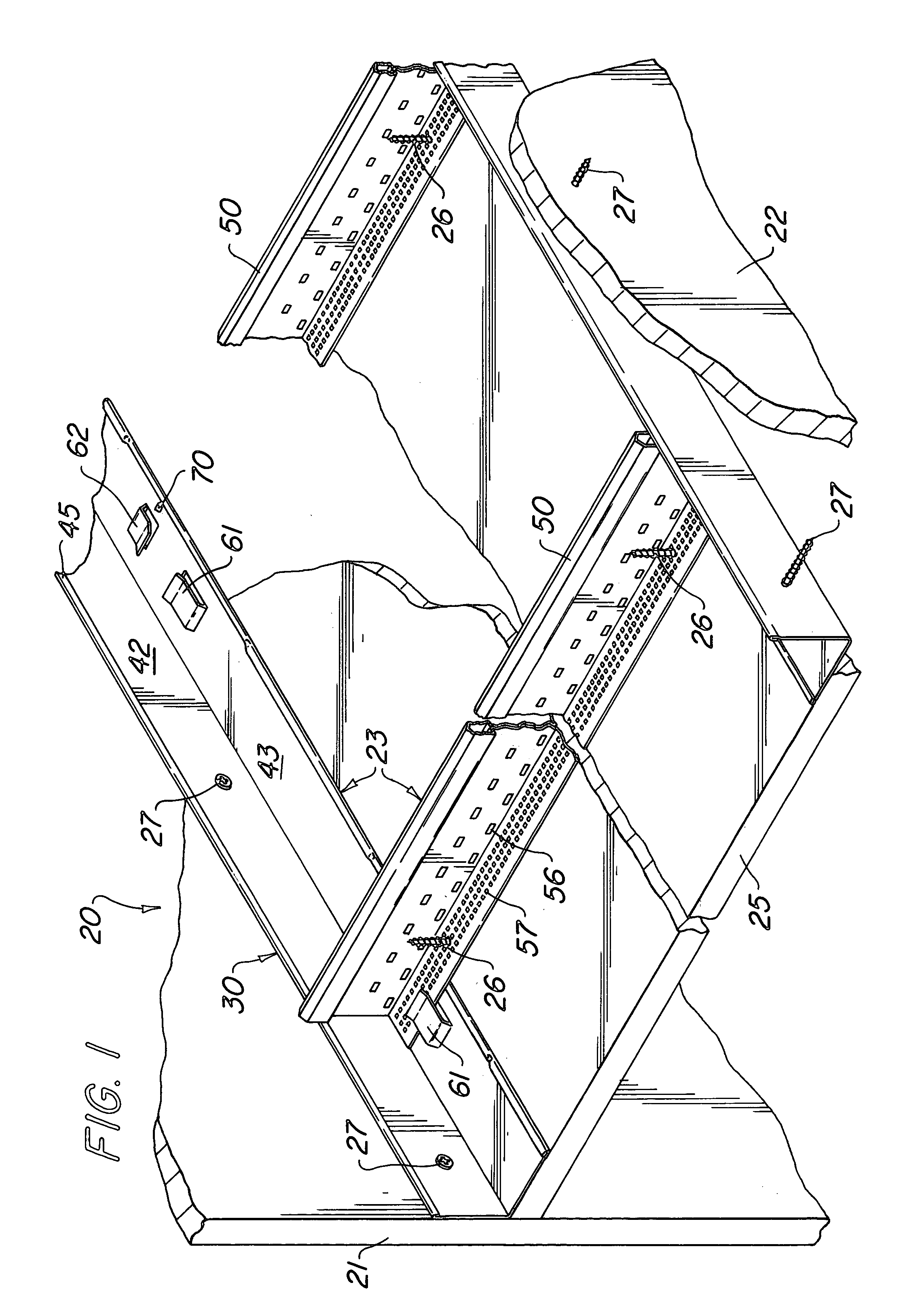
[0032] As seen in FIG. 1, a drywall ceiling 20 extends between opposing vertical room walls 21 and 22. The drywall ceiling 20 includes grid 23 having attached thereto panels 25 by self-tapping screws 26. The grid 23 includes wall molding 30 and beams 50. Molding 30 is secured to walls 21 and 22 by self-tapping screws 27.

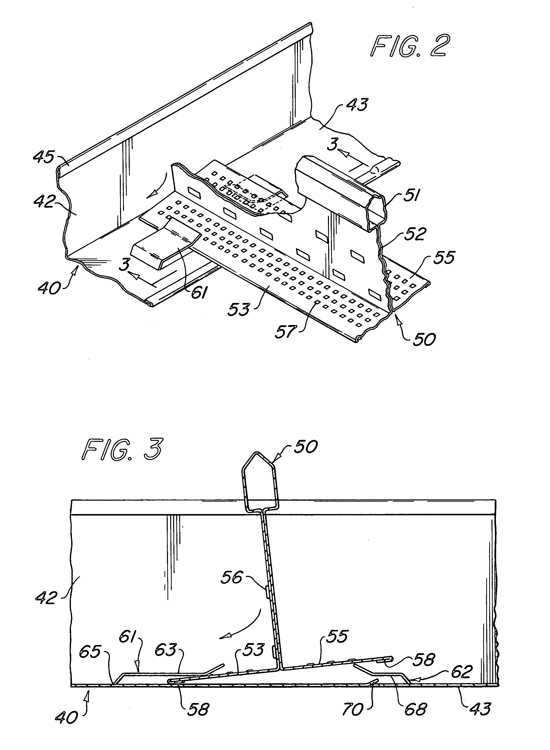
[0033] The wall moldings, as seen in the FIGS. 1 through 7, have spaced along the beam a pair 60 of opposing tabs 61 and 62. Tab 61 forms a hold-down tab wherein a tongue 63 is lanced from the ledge 43. Tongue 63 is biased downwardly toward the ledge. The hold-down tab 61 is integral with the ledge 43 at its pivot line 65 and then has a straight section 68 and an upturned section 69.

[0034] Positioned opposite to hold-down tab 61 is locking tab 62. Tab 62 is similar to tab 61 except the straight section 68 is shorter. Alongside the locking tab 62 is a ratchet tooth 70 which has a slope extending away from the hold-down tab 61, toward the pivot line 71 of locking tab...


PUM


Abstract

A wall molding for a drywall ceiling grid having a vertical leg that is attached to a wall, and a horizontal ledge that supports a beam extending outwardly from the wall, with the ledge having a pair of tabs and a ratchet tooth at regular intervals along the ledge that position and secure the beam end to the ledge.

Description

BACKGROUND OF THE INVENTION [0001] (1) Field of the Invention [0002] The invention is in the field of drywall interior ceilings. [0003] Preformed panels of drywall, sometimes called plasterboard, are affixed by self-tapping screws to a metallic grid suspended below a structural ceiling. The screws pass through flanges of beams in the grid. [0004] In short spans of ceiling, the beams are suspended only on a molding extending along the walls. On long spans of ceiling, the beams are also suspended between the walls by wires embedded in the structural ceiling. [0005] (2) The Prior Art [0006] There is shown in U.S. Pat. No. 6,722,098, incorporated herein by reference, a beam for a grid in a ceiling that has panels of drywall affixed to the ceiling grid by self-tapping screws. Such beams generally extend from wall to wall in a room, and rest on a wall molding having a right angle in its cross section, with the vertical leg of the angle affixed to the wall, and a horizontal ledge extending...

Claims


Application Information

Patent Timeline
Patent Type & Authority Applications(United States)
IPC IPC(8): E04B9/00
CPCE04B9/30E04B9/127
Inventor PLATT, WILLIAM J.
Owner WORTHINGTON ARMSTRONG VENTURE
Why Eureka
Try Eureka