Cooling of extruded and compression molded materials

a technology of applied in the field of cooling extruded and molded materials, can solve the problems of reducing the supply of wood in the world's forests for construction and other purposes, increasing the cost of wood, and retaining moisture, so as to improve the structural, physical and aesthetic characteristics, the effect of efficient cooling of the manufactured product or articl

Inactive Publication Date: 2006-01-19
CRANE PLASTICS PARTNERSHIP
View PDF18 Cites 21 Cited by
  • Summary
  • Abstract
  • Description
  • Claims
  • Application Information

AI Technical Summary

Benefits of technology

[0005] In the present invention, a product or article is manufactured by a desired technique such as, but not limited to, extrusion, compression molding, injection molding, or other similar, suitable, or conventional manufacturing techniques. The product is then cooled by subjecting it to a cooling fluid including, but not limited to, direct contact with a liquid cryogenic fluid. The present invention can be used alone or in conjunction with other known or later developed cooling methods. Accordingly, the present invention can more thoroughly and efficiently cool the manufactured product or article to a desired level. This can lead to faster production times as well as a product having improved structural, physical, and aesthetic characteristics.

Problems solved by technology

The supply of wood in the world's forests for construction and other purposes is dwindling.
Consequently, the supply of wood from mature trees has become a concern in recent years, and the cost of wood has risen.
In addition, cellulosic / polymer composites have enhanced resistance to moisture, and it is well known that the retention of moisture is a primary cause of the warping, splintering, and discoloration of natural woods.
However, many attempts to make products from cellulosic / polymer composite materials have failed due to poor or improper manufacturing techniques.

Method used


Image

  • Cooling of extruded and compression molded materials
  • Cooling of extruded and compression molded materials
  • Cooling of extruded and compression molded materials

Examples


Embodiment Construction

)

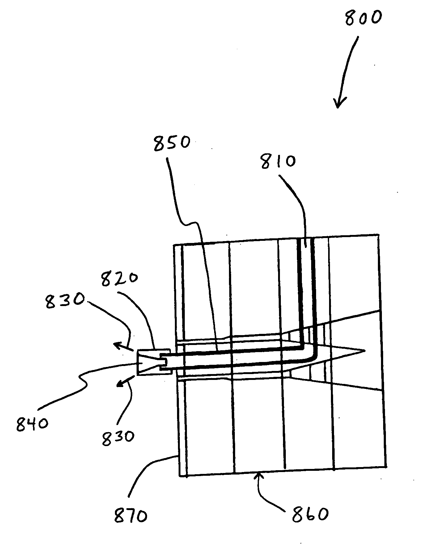
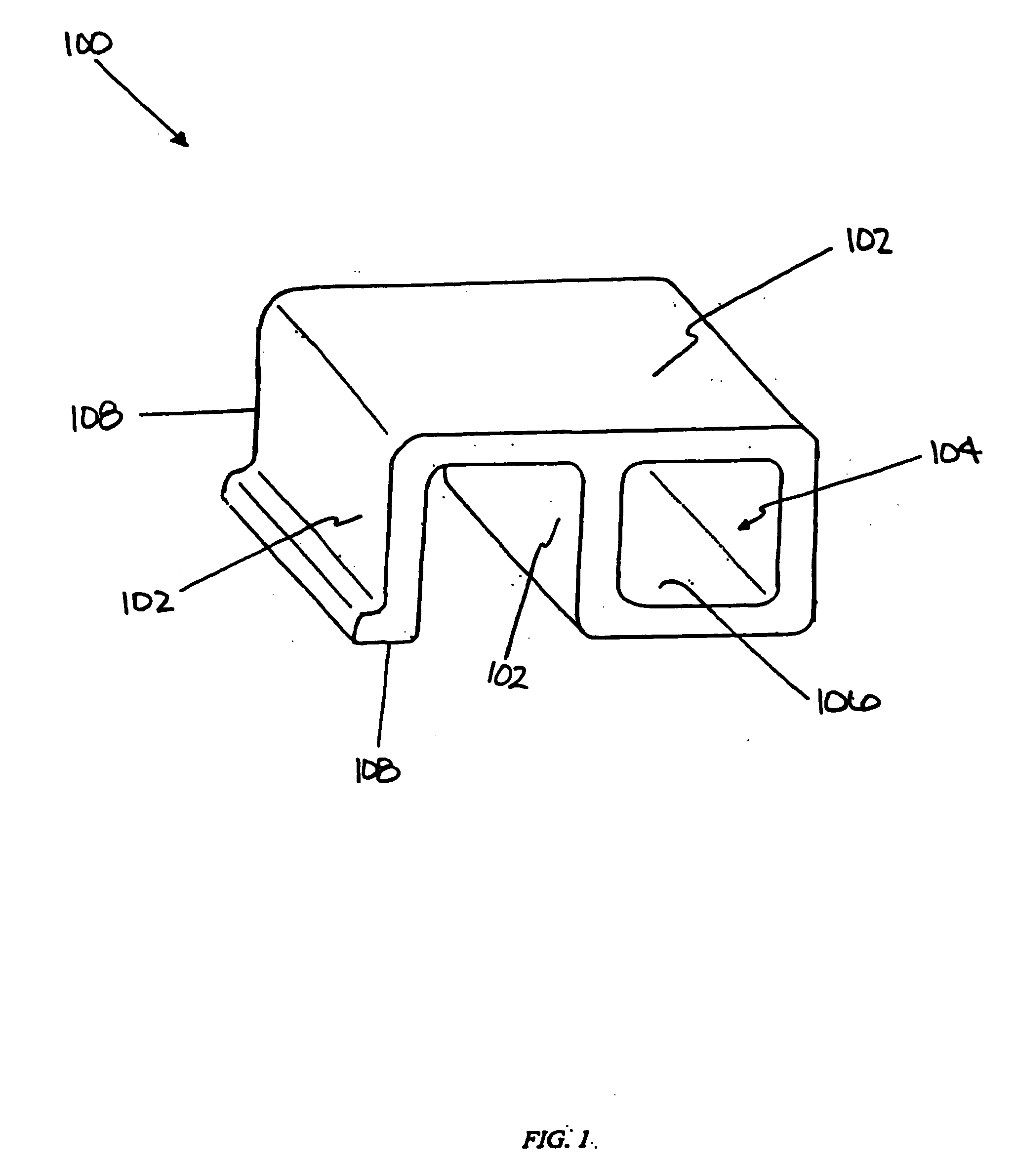
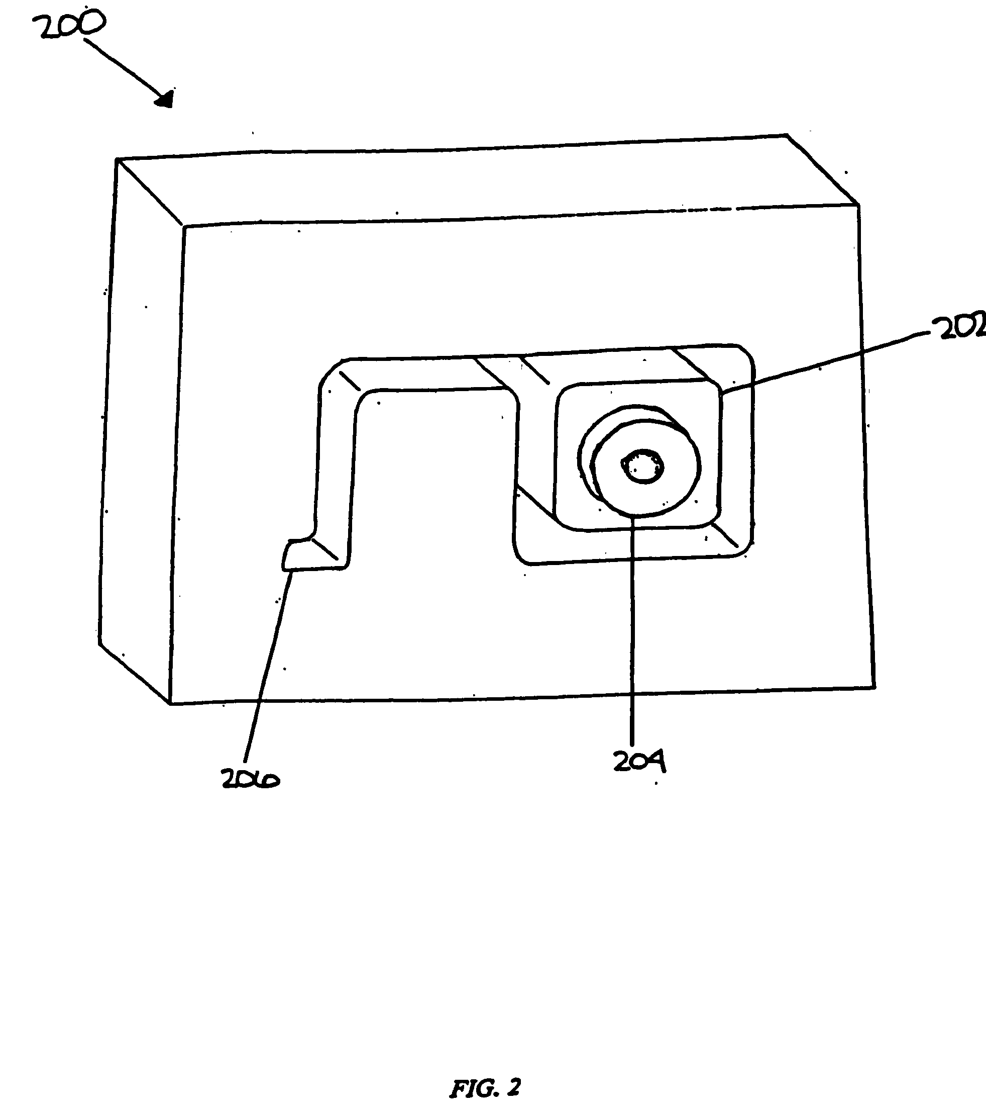
[0019] The present invention is directed to a system and method for cooling manufactured articles or products. It is not intended to limit the present invention to particular manufacturing techniques or particular materials. The present invention may be used to cool articles or products made by variety of different manufacturing techniques. Examples of manufacturing techniques that may utilize the present invention include, but are not limited to, extrusion (including co-extrusion), compression molding, injection molding, and other known, similar, or conventional techniques for manufacturing products or articles from plastic, wood, metal, mixtures of these materials, or other materials used to make products.

[0020] The present invention is particularly useful for cooling plastics, polymers, and cellulosic / polymer composite materials that have been extruded or molded. The materials that may be used to make cellulosic / polymer composites include, but are not limited to, cellulosic fil...


PUM

PropertyMeasurementUnit
temperatureaaaaaaaaaa

Abstract

The present invention relates to a system and a method for cooling extruded and molded materials. The present invention is especially useful to thoroughly cool an extrudate by directing a cooling fluid toward a surface of the extrudate (e.g., an interior surface that defines a hollow portion of an extrudate). Hollows may be created in order to reduce material, weight, and / or processing time. A cooling fluid is diverted toward the surface of the extrudate so as to cool the material and assist in solidification. A baffle may serve to divert the cooling fluid in the desired direction. In another example, the extrudate may be partially or totally immersed in a liquid cryogenic fluid. Increases in production line throughput may result by rapidly cooling the molded material. In addition, the more efficient cooling may be achieved with a lesser amount of the cooling fluid, and the velocity and temperature of the cooling fluid may be reduced. Other uses for the present invention include injection molding, compression molding, gas assist molding, and co-extrusion.

Description

[0001] This is a continuation of U.S. application Ser. No. 10 / 280,735, filed Oct. 25, 2002, which is a continuation-in-part of U.S. application Ser. No. 10 / 131,578, filed Apr. 24, 2002, now U.S. Pat. No. 6,637,213, which is a continuation-in-part of U.S. application Ser. No. 10 / 025,432, filed Dec. 19, 2001, now U.S. Pat. No. 6,708,504, which is a continuation-in-part of U.S. application Ser. No. 09 / 766,054, filed Jan. 19, 2001, now U.S. Pat. No. 6,578,368, each of which is hereby incorporated by reference in its entirety.BACKGROUND AND SUMMARY OF THE INVENTION [0002] The present invention relates generally to a system and method for cooling manufactured articles and, more particularly, to a system and method for cooling extruded and molded materials with a fluid that is below about 80 degrees Fahrenheit. The present invention may also be used in other types of manufacturing techniques in which the output or material must be cooled from a heated state. The present invention includes ...

Claims


Application Information

Patent Timeline
Patent Type & Authority Applications(United States)
IPC IPC(8): B05B3/00F25D13/06B29D31/00B29C35/02D01D5/00B29C35/16B29C44/22B29C48/12B29C48/21B29C48/32B29C48/49B29D99/00F25B9/00
CPCB29C35/16B29C44/22B29C47/0028B29C47/12B29C47/56F25B9/002B29C2035/1616B29C2035/165B29C2035/1658B29K2001/00B29L2031/60B29C47/882B29C48/09B29C48/11B29C48/12B29C48/304B29C48/34B29C48/49B29C48/9115B29C48/919B29C48/904B29C48/908B29C48/21
Inventor HUTCHISON, HERBERT L.BRANDT, JEFFREY R.
Owner CRANE PLASTICS PARTNERSHIP
Why Eureka
Try Eureka