Plate heat exchanger with condensed fluid separating functions and its manufacturing method

a technology of condensed fluid and heat exchanger, which is applied in the direction of defrosting, separation process, domestic cooling apparatus, etc., can solve the problems of heat transfer loss, inability to reduce the size and weight of the heat exchanger, and structural inability to separate the condensed fluid by itself, so as to reduce the manufacturing cost, prevent the excessive installation space and heat transfer loss, and reduce the effect of heat loss

Active Publication Date: 2006-01-19
IND TECH & SERVICES KOREA CO LTD
View PDF9 Cites 10 Cited by
  • Summary
  • Abstract
  • Description
  • Claims
  • Application Information

AI Technical Summary

Benefits of technology

[0010] The present invention is designed to solve the problems of the prior art, and therefore it is an object of the present invention is directed to preventing an excessive installation space and a heat transfer loss that are caused in the prior art by connection pipes between a condensed fluid separator and a plate heat exchanger, and also remarkably reducing a manufacturing cost.
[0011] In order to accomplish the above object, the present invention provides a plate heat exchanger that is small and ligh

Problems solved by technology

The conventional plate heat exchanger is structurally not capable of separating the condensed fluid by itself, so a separator is additionally installed out cf it and the separator is connected to the chiller and the reheater by means of external pipes.
Thus, th

Method used


Image

  • Plate heat exchanger with condensed fluid separating functions and its manufacturing method
  • Plate heat exchanger with condensed fluid separating functions and its manufacturing method
  • Plate heat exchanger with condensed fluid separating functions and its manufacturing method

Examples


Embodiment Construction

[0016] Hereinafter, the present invention will be described in more detail referring to the drawings.

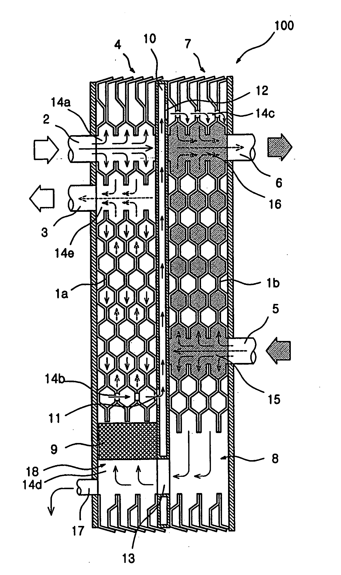
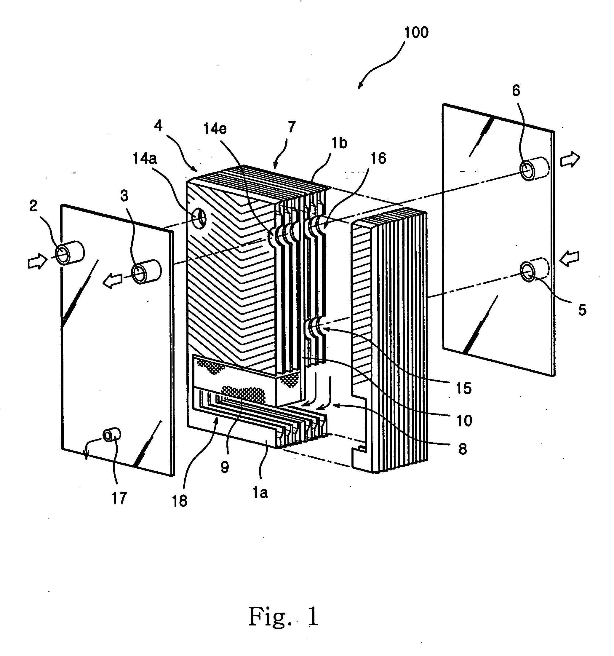
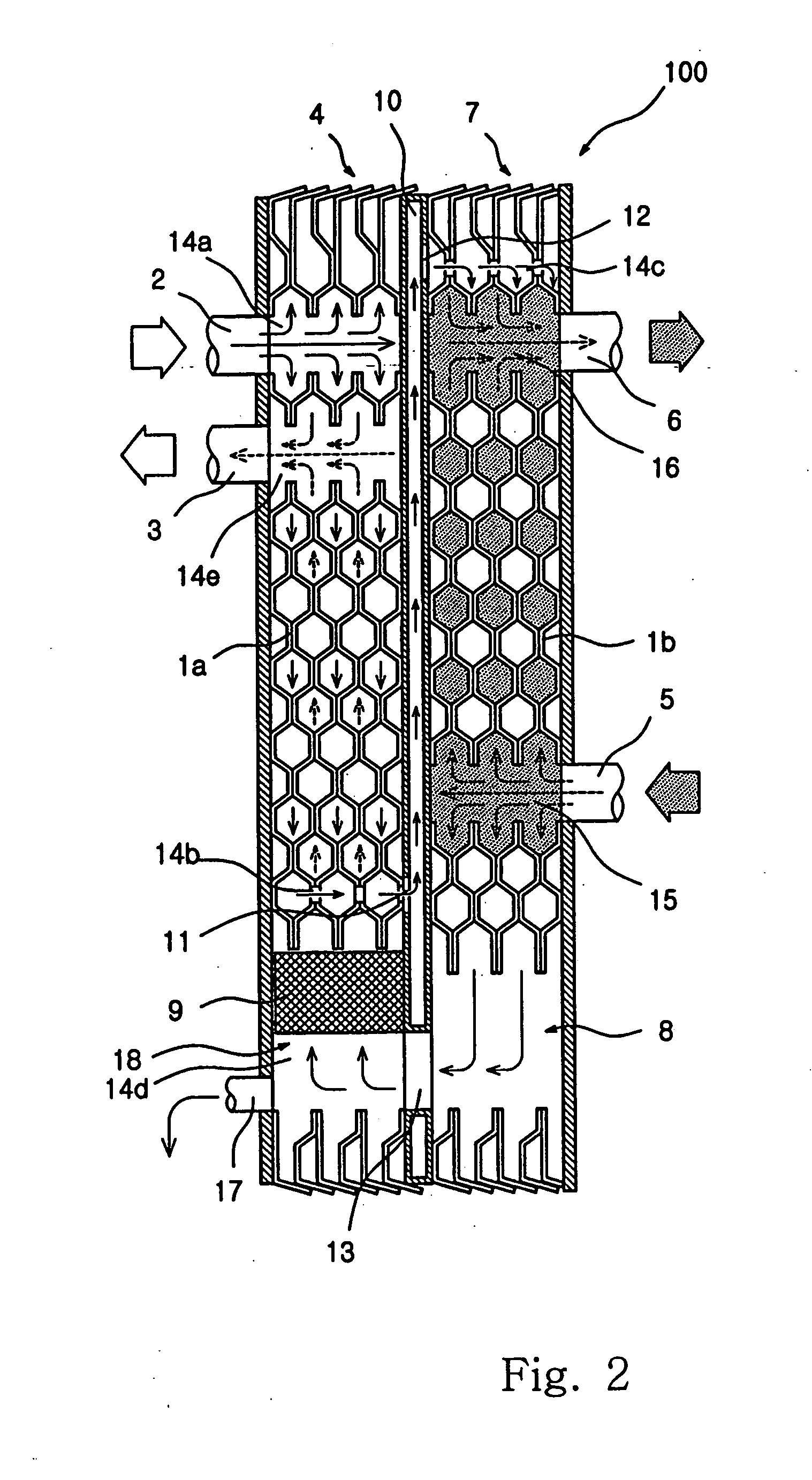
[0017]FIG. 1 is an exploded perspective view showing a plate heat exchanger according to the present invention, FIG. 2 is a sectional view of the plate heat exchanger, and FIG. 3 shows flow of compressed air and working fluid in the plate heat exchanger.

[0018] As shown in FIGS. 1 and 2, an integrated plate heat exchanger 100 with a condensed fluid separating function according to the present invention includes a reheater 4 having a plurality of wrinkled plates 1a laminated therein, wherein two internal air channels are formed by means of the laminated plates 1a so as to be connected to an introduction hole 2 and a discharge hole 3; and a chiller 7 having a plurality of wrinkled plates 1b laminated to form two internal channels therein, wherein a working fluid inlet hole 5 and a working fluid outlet hole 6 connected to a working fluid channel among the channels are formed therein, a...


PUM


Abstract

A plate heat exchanger with a condensed fluid separating function, which includes a reheater having plural laminated wrinkled plates and introduction and discharge holes connected to different compressed air channels therein; a chiller having plural laminated wrinkled plates, working fluid inlet and outlet holes connected to a working fluid channel therein, and compressed air channels formed therein; and a wall-shaped pipe configured for partitioning the reheater and the chiller with providing a flow line to communicate a compressed air with he reheater and the chiller. An adiabatic expansion chamber is formed in a lower portion of the chiller on a flow line for the compressed air cooled in the chiller to move toward the reheater. A condensation chamber is formed in a lower portion of the reheater connected to the adiabatic expansion chamber. A condensation mesh sieve and a drainage hole are formed in the condensation hole.

Description

BACKGROUND OF THE INVENTION [0001] 1. Field of the Invention [0002] The present invention relates to a plate heat exchanger with a condensed fluid separating function and its manufacturing method, and more particularly to an integrated plate heat exchanger with a condensed fluid separating function in which a separator connected to outside of the plate heat exchanger by means of a pipe is integrally mounted in the plate heat exchanger so that a conventional heat transfer loss caused by fluid channel for connecting the separator to a reheater and a chiller is prevented, a discharging efficiency of a condensed fluid is maximized, and a cooling air drier may become smaller and lighter, and its manufacturing method. [0003] 2. Description of the Prior Art [0004] A plate heat exchanger is used for changing a hot compressed air into a cold compressed air, and generally used as a component of an air drier. Such an air drier changes a hot and humid saturated air into a cold and dry compresse...

Claims


Application Information

Patent Timeline
IPC IPC(8): F25B7/00F25D21/00F25D17/06
CPCB01D5/0015B01D5/0072B01D5/009F28F3/04F28D9/005F28D9/0093F28B9/08
Inventor LEE, BYEONG-SEUNG
Owner IND TECH & SERVICES KOREA CO LTD
Why Eureka
Try Eureka