
Positive electrode for non-aqueous electrolyte battery, negative electrode for non-aqueous electrolyte battery, separator for non-aqueous electrolyte battery, and non-aqueous electrolyte battery using them

Inactive Publication Date: 2009-11-26
SANYO ELECTRIC CO LTD
View PDF14 Cites 11 Cited by
  • Summary
  • Abstract
  • Description
  • Claims
  • Application Information

AI Technical Summary

Benefits of technology

[0037]In recent years, in the batteries employing wound electrode assemblies, the tension in the electrode assemblies has tended to be higher because, for example, the winding tension has tended to be increased, and consequently, the non-aqueous electrolyte is difficult to permeate and diffuse. Therefore, when the present invention is applied to such a battery, the above-described advantageous effects are exhibited further.
[0038]It is desirable that the battery case have a cylindrical shape or a prismatic shape.
[0039]The batteries in which the battery case has a cylindrical or prismatic shape can benefit more from the above-described advantageous effects because they have more excess space than those with a thin-type battery case such as laminate batteries and correspondingly they can contain a large amount of excess electrolyte.
[0040]It is desirable that the porous layer comprise a binder and inorganic-material-based microparticles comprising at least one substance selected from the group consisting of alumina and titania.
[0041]When using these materials, it is possible to reliably provide appropriate space (gap) that can ensure permeation of the non-aqueous electrolyte since the porous layer is constituted by non-oriented substances that are in microparticle state. Moreover, these materials are impervious to quality degradation in the battery because they have high mechanical strength and high thermal stability.
[0042]It should be noted however that it is also possible to use not only alumina and / or titania but also other ceramic materials such as zirconia.

Problems solved by technology

However, the non-aqueous electrolyte batteries have not yet satisfied the requirements sufficiently.
Consequently, problems in battery design that pertain to permeation and retention of electrolyte in the electrode have become more evident than they were at the early stage of the lithium-ion battery development.

Method used


Image

  • Positive electrode for non-aqueous electrolyte battery, negative electrode for non-aqueous electrolyte battery, separator for non-aqueous electrolyte battery, and non-aqueous electrolyte battery using them
  • Positive electrode for non-aqueous electrolyte battery, negative electrode for non-aqueous electrolyte battery, separator for non-aqueous electrolyte battery, and non-aqueous electrolyte battery using them
  • Positive electrode for non-aqueous electrolyte battery, negative electrode for non-aqueous electrolyte battery, separator for non-aqueous electrolyte battery, and non-aqueous electrolyte battery using them

Examples


embodiments

Preliminary Experiment 1

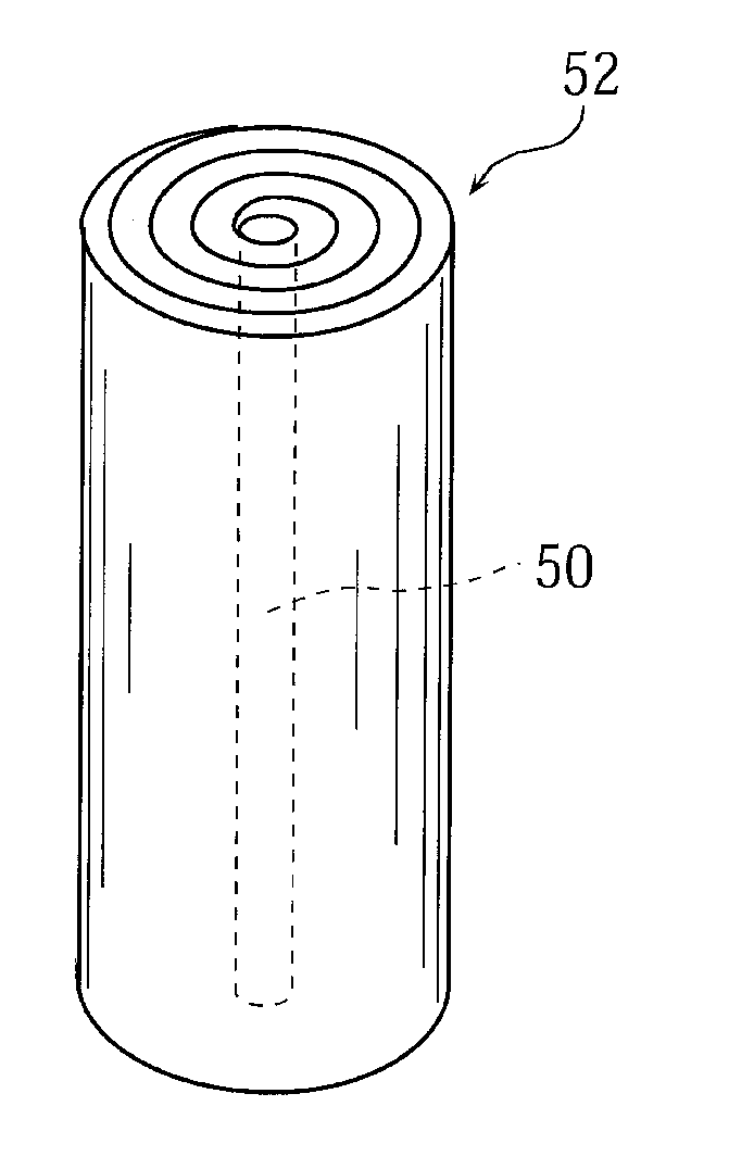
[0081]The condition of electrolyte impregnation in the wound electrode assembly was observed by varying the conditions of filling the electrolyte into the battery (i.e., without carrying out compression or decompression after filling the electrolyte) to evaluate the condition of permeation and diffusion of the electrolyte in an actual battery. The results are shown in Table 1.

(Battery Used)

[0082]The battery that was used to carry out this experiment had the same configuration as described in the “Best Mode for Carrying out the Invention” (hereinafter simply referred to as the “best mode”) above, except that the battery was a 18650-type cylindrical battery (in which the maximum height of the wound electrode assembly is 59.5 mm and the wound electrode assembly is a cylindrical shape, unlike a laminate battery in which the wound electrode assembly is in a flat shape) and that it used the positive electrode and the separator as described below. It should be noted...

experiment 2

Preliminary Experiment 2

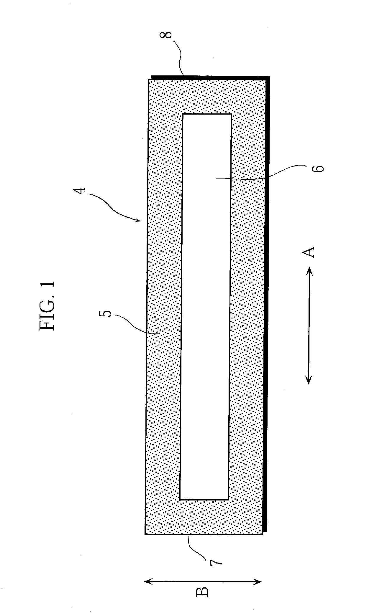
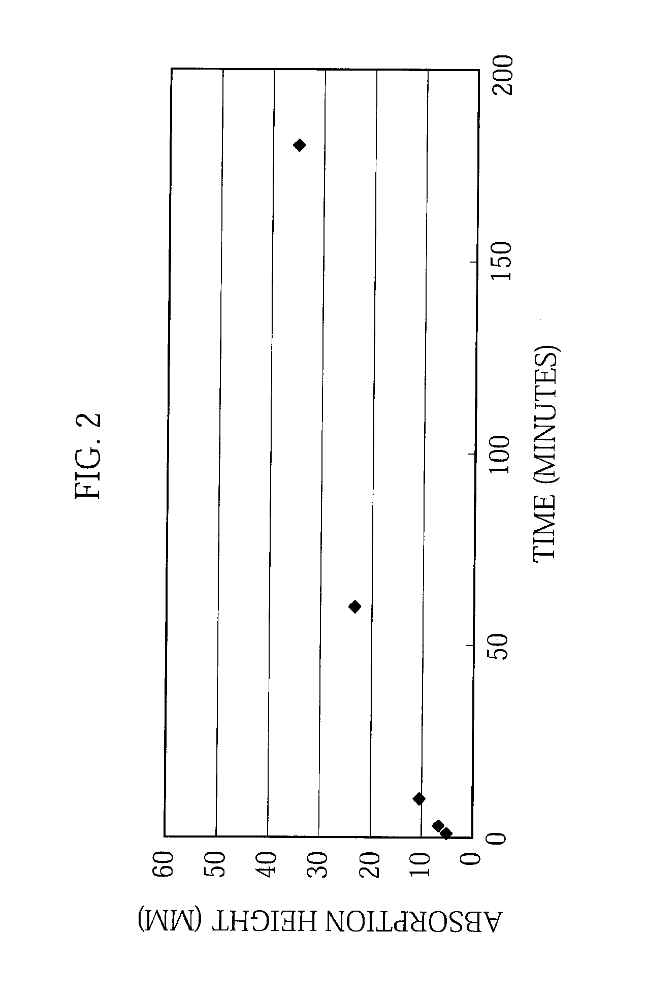
[0095]Bearing in mind the results of the electrolyte permeation in the cylindrical electrode assembly shown in the preliminary experiment 1, a comparison was made about the electrolyte absorption conditions for the electrolyte in separators, for the purpose of identifying permeation and diffusion paths of the electrolyte. Specifically, an electrolyte absorbency evaluation and an air permeability measurement for separators were carried out.

Separators Used

[0096]The separators used in this experiment were: PE separators (one with a large pore size and one with a small pore size), a layered separator of PP(polypropylene) / PE / PP (in which PP film / PE film / PP film were bonded by thermocompression bonding), and a porous resin coated separator in which a porous layer made of PA was formed on a PE separator (the same separator as the one shown in the foregoing best mode). The separators were cut into a shape having a width of 1.5 cm and a length of 5.0 cm to make the ev...

experiment 3

Preliminary Experiment 3

[0111]Bearing in mind the results of permeation of the electrolyte in the cylindrical electrode assembly, shown in the preliminary experiment 1, a comparison was made about electrolyte absorption conditions for the electrolyte in electrodes, for the purpose of identifying permeation and diffusion paths of the electrolyte.

(Electrodes Used)

[0112]The electrodes used here were the same electrodes (positive electrode and negative electrode, samples 11 and 12 in Table 4) as described in the preliminary experiment 1 (the electrodes for 18650 cylindrical battery) and the negative electrodes having a porous layer formed thereon (samples 13 to 15 in Table 4). The electrodes have a width of 1.5 cm and a length of 5.0 cm.

[0113]The porous layer was prepared in the following manner. First, titania (TiO2, average particle size 31 nm) and PVDF were mixed at a mass ratio of 95:5, and thereafter, NMP was used as the solvent to prepare a slurry in which the viscosity was contro...


PUM


Abstract

The present invention provides a non-aqueous electrolyte battery, etc. that can reduce the manufacturing cost of the battery, meet the need for increased battery capacity, and at the same time improve various battery characteristics, such as high-rate charge-discharge capability, high-temperature cycle performance, and storage performance.A porous layer (32) is disposed between a separator and a negative electrode (13). The porous layer has a non-aqueous electrolyte permeability higher than that in TD of the separator. An excess electrolyte is contained in at least a portion of an internal space of a battery case that is other than an electrode assembly, and the excess electrolyte and at least a portion of the porous layer are in contact with each other.

Description

TECHNICAL FIELD[0001]The present invention relates to non-aqueous electrolyte batteries, such as lithium-ion batteries and polymer batteries, and electrodes for the non-aqueous electrolyte batteries. More particularly, the invention relates to, for example, a battery structure that is excellent in battery performance relating to electrolyte permeability (such as cycle performance, storage performance, and safety) and that exhibits high reliability even with a battery design that features high capacity and high power.BACKGROUND ART[0002]Mobile information terminal devices such as mobile telephones, notebook computers, and PDAs have become smaller and lighter at a rapid pace in recent years. This has led to a demand for higher capacity batteries as the drive power source for the mobile information terminal devices. With their high energy density and high capacity, non-aqueous electrolyte batteries that perform charge and discharge by transferring lithium ions between the positive and ...

Claims


Application Information

Patent Timeline
IPC IPC(8): H01M6/10H01M2/14H01M4/131H01M4/133H01M4/52H01M4/525H01M10/0525H01M10/058H01M10/0587H01M10/36H01M50/449H01M50/457H01M50/469H01M50/489
CPCH01M2/1673H01M2/1686H01M2/18H01M4/131H01M4/133Y02T10/7011H01M10/0525H01M10/058H01M10/0587Y02E60/122H01M4/525Y02E60/10H01M50/46H01M50/449Y02P70/50H01M50/489H01M50/469H01M50/457H01M10/05H01M50/491H01M50/102H01M50/431H01M50/443H01M50/414H01M10/42H01M4/587H01M50/417H01M2010/4292Y02T10/70
Inventor BABA, YASUNORIIMACHI, NAOKISIBUTANI, YUKOMIKAMI, AKIRAFUJIMOTO, HIROYUKIMATSUTA, SHIGEKIFUJITANI, SHIN
Owner SANYO ELECTRIC CO LTD
Learn More