
Apparatus for cryogenic fluids having floating liquefaction unit and floating regasification unit connected by shuttle vessel, and cryogenic fluid methods

a technology of cryogenic fluids and apparatus, which is applied in the direction of lighting and heating apparatus, packaging goods type, container discharging methods, etc., can solve the problems of affecting the utilization rate of gas

Inactive Publication Date: 2006-01-19
MUSTANG ENG
View PDF4 Cites 54 Cited by
  • Summary
  • Abstract
  • Description
  • Claims
  • Application Information

AI Technical Summary

Benefits of technology

[0021] It is an object of the present invention to provide for improved apparatus and methods for processing, transporting, and / or storing LNG.

Problems solved by technology

However, given certain barriers of geography, economics, and / or politics, transportation by pipeline is not always possible, economic or permitted.
Without an effective way to transport the natural gas to a location where there is a commercial demand, the gas may be burned as it is produced, which is wasteful or reinjected into a subsurface reservoir which is costly and defers the utilization of the gas.
Of the known liquid energy gases, liquid natural gas is the most difficult to handle because it is so intensely cold.

Method used


Image

  • Apparatus for cryogenic fluids having floating liquefaction unit and floating regasification unit connected by shuttle vessel, and cryogenic fluid methods
  • Apparatus for cryogenic fluids having floating liquefaction unit and floating regasification unit connected by shuttle vessel, and cryogenic fluid methods
  • Apparatus for cryogenic fluids having floating liquefaction unit and floating regasification unit connected by shuttle vessel, and cryogenic fluid methods

Examples


Embodiment Construction

[0032] While some descriptions of the present invention may make reference to natural gas and to liquified natural gas (“LNG”), it should be understood that the present invention is not limited to utility with natural gas and LNG, but rather has broad utility with gases and cryogenic fluids in general, preferably cryogenic fluids formed from flammable gases.

[0033] The apparatus of the present invention will find utility for processing, storing, and / or transporting (i.e., including but not limited to, receiving, dispensing, distributing, moving) gases and cryogenic fluids, a non-limiting example of which are natural gas and liquified natural gas (“LNG”).

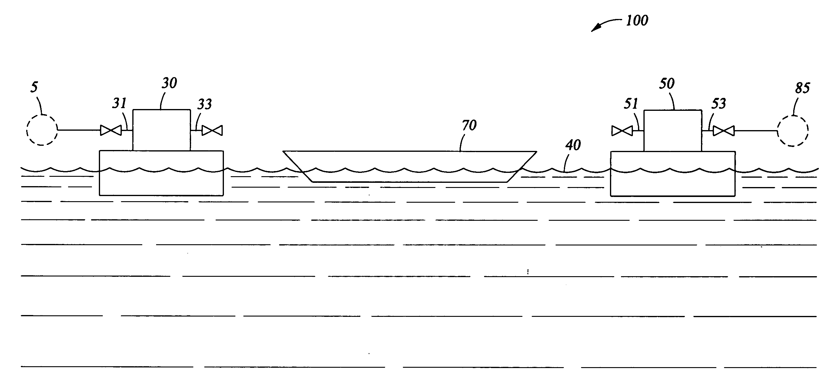
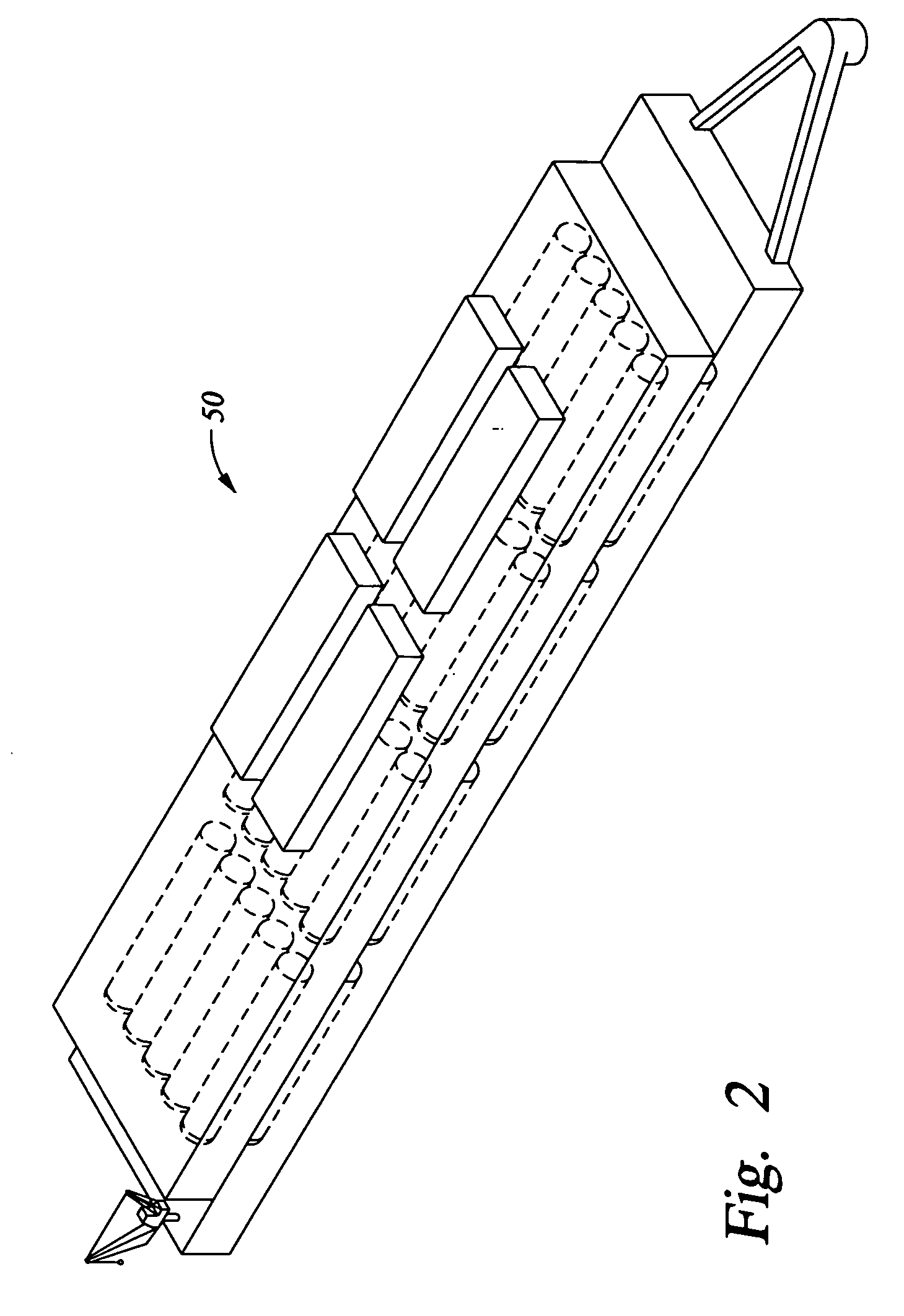
[0034] According to the present invention, there are provided a floating liquefaction unit, a floating regasification unit, a shuttle vessel traveling therebetween.

[0035] Further according to the present invention, there is provided a system comprising a floating liquefaction unit receiving a gas from a source, a shuttle vessel for...


PUM

PropertyMeasurementUnit
boiling pointaaaaaaaaaa
temperatureaaaaaaaaaa
pressureaaaaaaaaaa

Abstract

Methods and systems for transportation of a cryogenic fluid. The system includes a floating liquefaction unit receiving a gas from a source, a shuttle vessel for carrying liquefied gas away from the liquefaction unit, and a floating regasification unit for receiving the liquefied gas from the vessel, regassifying the liquefied gas and providing the gas to a distribution system.

Description

RELATED APPLICATION DATA [0001] This application is a continuation-in-part (CIP) of U.S. patent application Ser. No. 10 / 894,355, filed Jul. 18, 2004, the disclosure of which is herein incorporated by reference.BACKGROUND OF THE INVENTION [0002] 1. Field of the Invention [0003] The present invention relates to cryogenic fluids. In another aspect, the present invention relates to methods and apparatus for processing, transporting and / or storing cryogenic fluids. In even another aspect, the present invention relates to receiving and / or dispensing terminals for cryogenic fluids and to methods of receiving, dispensing and / or storing cryogenic fluids. In still another aspect, the present invention relates a cryogenic fluid system having a floating liquefaction unit receiving a gas from a source, a shuttle vessel for carrying liquefied gas away from the liquefaction unit, and a floating regasification unit for receiving the liquefied gas from the vessel, regassifying the liquefied gas and ...

Claims


Application Information

Patent Timeline
Patent Type & Authority Applications(United States)
IPC IPC(8): F17C9/02F17C13/08F25J1/00
CPCF17C3/04F25J2290/72F17C9/02F17C9/04F17C13/026F17C2201/0157F17C2201/035F17C2201/052F17C2203/0341F17C2203/0617F17C2203/0636F17C2203/0678F17C2205/0142F17C2205/0146F17C2221/033F17C2223/0161F17C2223/033F17C2225/0123F17C2225/035F17C2227/0135F17C2227/0311F17C2227/0316F17C2227/0323F17C2227/0327F17C2227/0393F17C2227/044F17C2250/0439F17C2265/05F17C2270/0105F17C2270/0113F17C2270/0123F25J1/0022F25J1/0035F25J1/0037F25J1/004F25J1/0045F25J1/0202F25J1/0278F25J3/0209F25J3/0233F25J3/0242F25J2200/02F25J2205/04F25J2220/62F25J2220/64F25J2240/02F25J2245/02F25J2270/04F17C5/06
Inventor HUBBARD, BRADFORD S.BAUDAT, NED P.WORTHINGTON, W. SCOTT
Owner MUSTANG ENG
Learn More