
Welding wire package with lifting strap

Active Publication Date: 2006-01-19
LINCOLN GLOBAL INC
View PDF32 Cites 4 Cited by
  • Summary
  • Abstract
  • Description
  • Claims
  • Application Information

AI Technical Summary

Benefits of technology

[0007] In accordance with the present invention, a welding wire package is provided which includes a lifting strap that cannot be pulled from the packaging but which is also easily separable from the packaging after the welding wire is consumed. In this respect, a package according to the present invention includes a lifting strap which interengages with the hold-down mechanism of the wire package to prevent removal of the strap until the welding wire is consumed.
[0009] A further object of the present invention is the provision of welding wire package which includes a lifting strap that prevents removal of the strap before the welding wire has been consumed.
[0010] Still a further object of the present invention is the provision of a welding wire package which includes a lifting strap that can be easily separated from the remaining package components after the welding wire has been consumed.
[0012] Yet another object of the present invention is the provision of a welding wire package which includes a lifting strap that is economical to produce, easy to use and either reuse or discard after use.

Problems solved by technology

As can be appreciated, large welding wire packages are heavy and require the use of lifts and other material transport devices to move the packages.
However, handles provide little benefit for larger wire packages.
As can be appreciated, the packing skid which is heavy and bulky, and often expensive, must be disposed of once the welding wire is consumed.
As can be appreciated, once the strap has been pulled from the packaging, it is difficult, if not impossible, to utilize the strap to lift the welding wire package.
Further, if the strap is securely affixed to the packaging, such as by staples, it is difficult to separate the strap from the packaging after the wire is consumed.

Method used


Image

  • Welding wire package with lifting strap
  • Welding wire package with lifting strap
  • Welding wire package with lifting strap

Examples


Embodiment Construction

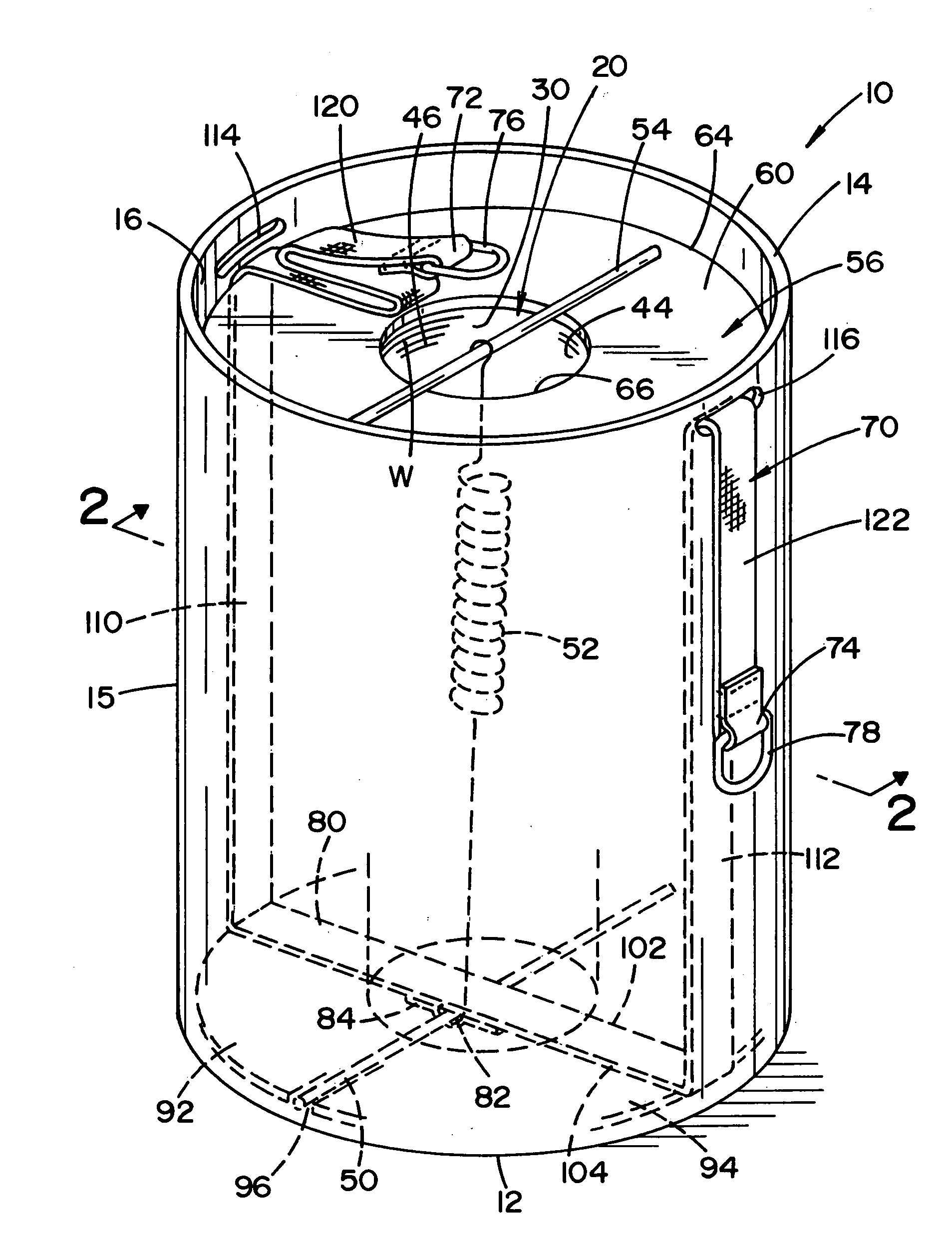
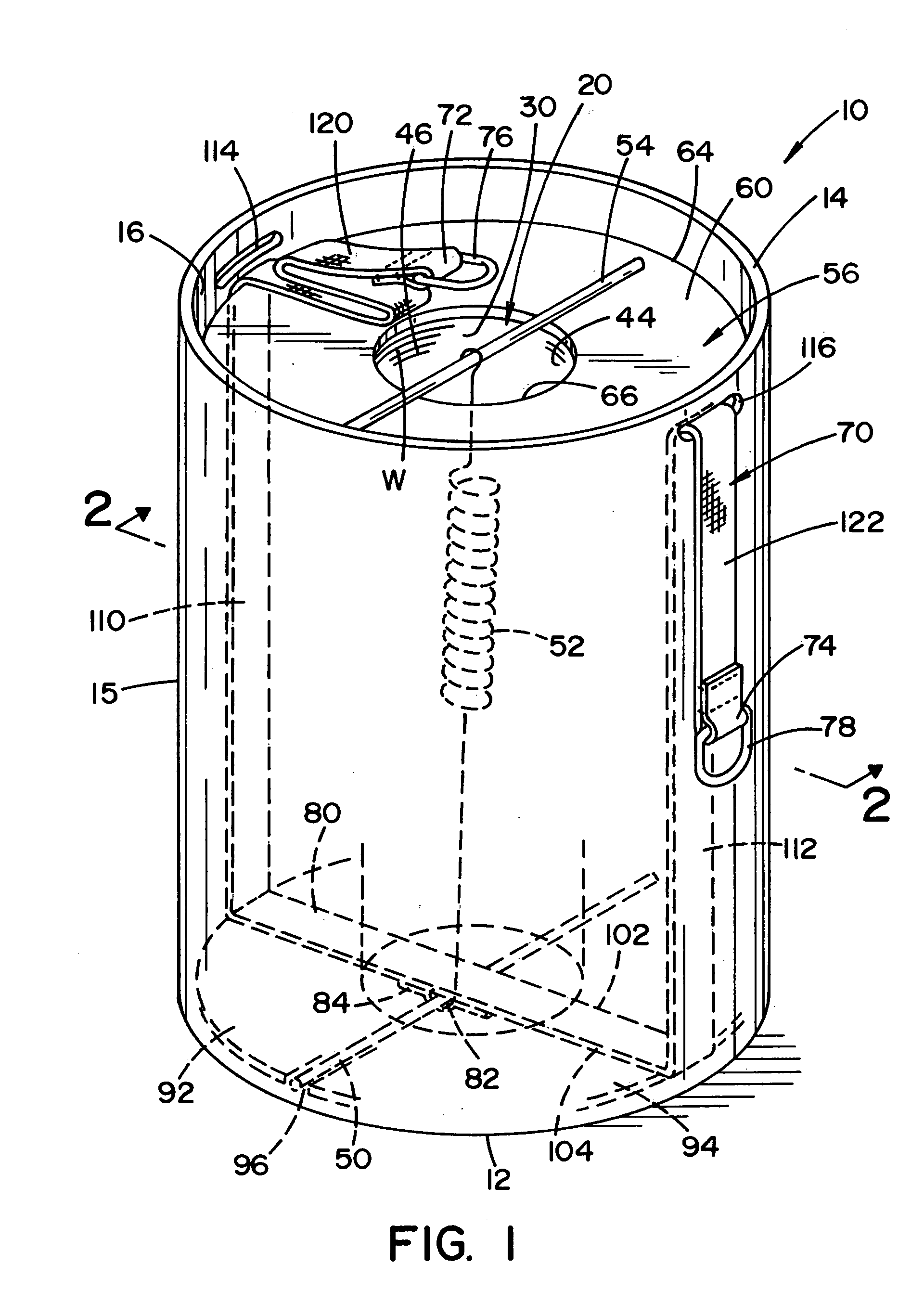
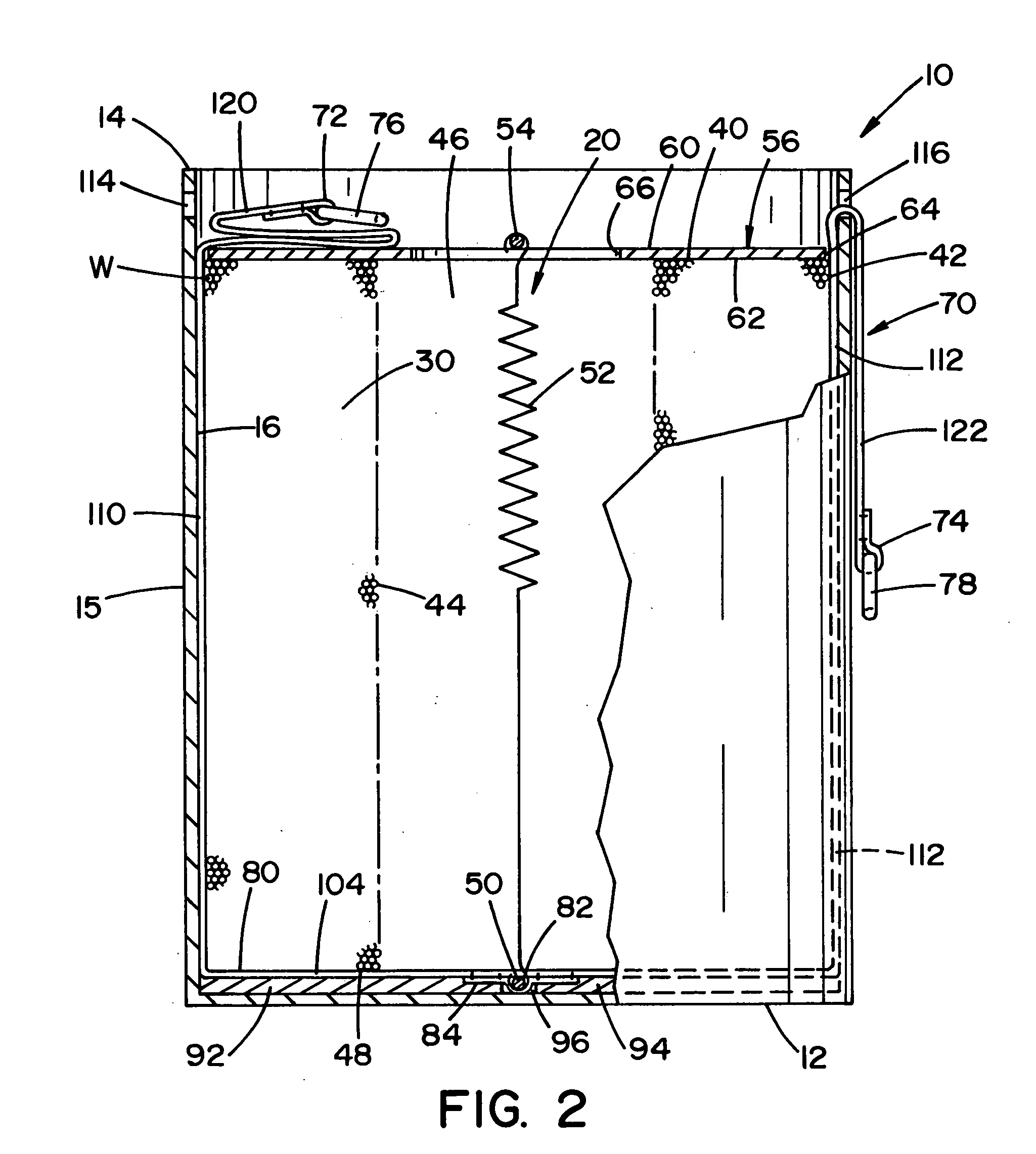
[0021] Referring now in greater detail to the drawing wherein the showings are for the purpose of illustrating preferred embodiments of the invention only, and not for the purpose of limiting the invention, FIGS. 14 illustrate a welding wire drum type package 10 wherein a wire W is stored in and paid out of the package which includes a bottom 12, a top 14, and a cylindrical side wall 15 having an inner surface 16. Package 10 can further include a cylindrical cardboard core (not shown) concentric with surface 16. Package 10 further includes a hold-down mechanism 20 which helps maintain a coil 30 of wire W and prevents coil 30 from shifting during transportation.

[0022] As is know, package 10 is loaded with wire W at the wire manufacturing facility and the wire is looped into the package to define a body of welding wire, namely, wire coil 30 having a top surface 40, an outer cylindrical surface 42 against surface 16 and an inner cylindrical surface 44. In this manner, a central vertic...


PUM


Abstract

A package for containing a coil of wire having an outer cylindrical surface extending about a coil axis, a top and an oppositely facing bottom has a base for supporting the bottom of a wire coil when the wire coil is in the package. At least one side wall extends upwardly from the base about an outer cylindrical surface of the wire coil and has an upper edge defining a top opening in the package for removing the wire. The packaging further includes a hold-down bar between the bottom of the wire coil and the base which is transverse to the axis of the wire coil, and a lifting strap having a first end, a second end and a base portion between the first and second ends and between the bottom of the wire and the base. The base portion has an opening and the hold-down bar extends through the opening.

Description

[0001] The present invention relates to welding wire packaging and more particularly to a welding wire package with an improved lifting strap configuration that cannot be easily removed until the welding wire is consumed. INCORPORATION BY REFERENCE [0002] Welding wire used in high production operations, such as robotic welding stations, is provided in a package generally having over 200 pounds of wire. The package is often a drum where a large volume of welding wire is looped in the drum around a central core or a central clearance bore. During transportation a hold down mechanism can be used to prevent the wire coil from shifting. To control the transportation and payout of the wire, it is standard practice to provide an upper retainer ring which can be utilized as a part of the hold down mechanism to prevent wire shifting. One such package is shown in Cooper U.S. Pat. No. 5,819,934 which is incorporated by reference herein as background material showing the same. Another such pack...

Claims


Application Information

Patent Timeline
IPC IPC(8): B65D85/00B65D85/66B65H18/28B65H55/04B23KB65DB65D85/04B65D88/54B65D90/00B65H49/08B65H49/38B66C1/18
CPCB65D85/04B65D88/54B65D90/0033B66C1/18B65H49/08B65H49/38B65D90/004B65D85/02B65D85/66
Inventor BARTON, DAVID J.
Owner LINCOLN GLOBAL INC
Learn More