
System and method for computing grasps for a robotic hand with a palm

a robotic hand and palm technology, applied in the field of robotics, can solve the problems of insufficient restraining force, inability to plan a predetermined configuration, and almost impossible to hold up with a precision grasp

Active Publication Date: 2006-01-19
STRIDER LABS
View PDF31 Cites 75 Cited by
  • Summary
  • Abstract
  • Description
  • Claims
  • Application Information

AI Technical Summary

Benefits of technology

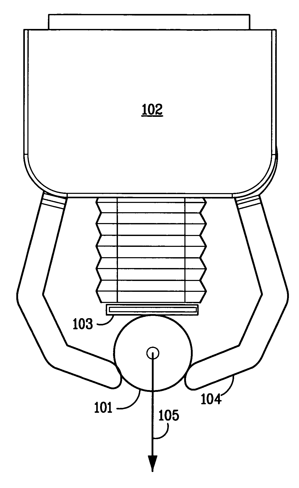
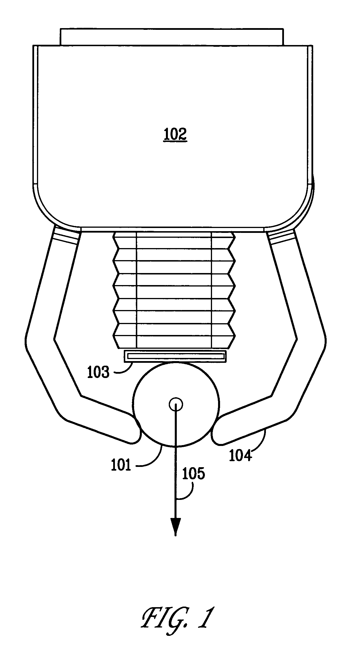
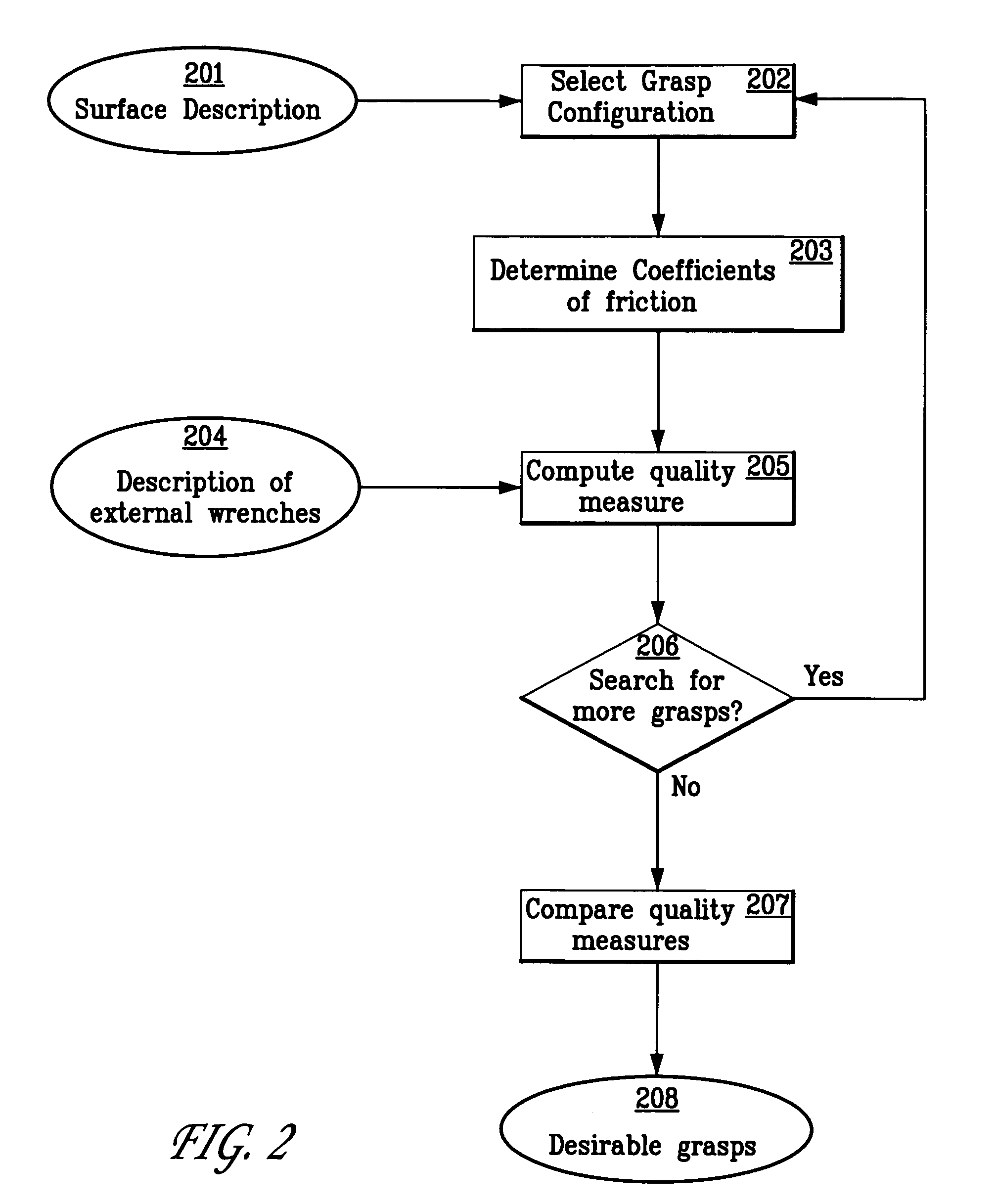
[0027] The present invention provides a system and method for automatically computing desirable palm grasp configurations of an object by a robotic hand. A description of the object's surface is obtained. A grasp configuration of a robotic hand comprising a palm and one or more fingers is selected, which specifies a hand configuration and joint variables of the hand and a plurality of contact points on the object's surface for the palm and fingers. The coefficient of friction at each of the contact points is determined, and a description of one or more external wrenches that may apply to the object is acquired. The ability of the robotic hand to hold the object against the external wrenches in the selected configuration is then computed.
[0028] In some embodiments, a plurality of grasp configurations may be selected by any means desirable, and compared to determine which are the most desirable. In other embodiments, the space of hand configurations, or the smaller space of palm contact configurations, may be searched to find the most desirable grasp configurations.
[0029] The desirability of a grasp configuration may be measured in various ways. In one embodiment, a quality measure is defined by solving a force optimization problem in which the largest force required to be applied by the robotic hand is minimized. In other embodiments, an approximation of the solution to the force optimization problem, or other methods, may be used.
[0030] The present invention also provides a computer-readable medium comprising program instructions for performing the steps of the method. Finally, the present invention may also be applied to precision grasps.

Problems solved by technology

Second, the robot will not have previously encountered every object, and will not have a pre-planned configuration to be used for grasping each object.
Consider grasping a large frying pan by its handle; it is almost impossible to hold it up with a precision grasp.
Similarly, when other large forces may occur, it is often the case that only a palm grasp can provide sufficient force to secure the object.
A precision grasp again provides insufficient restraining force in this situation and therefore cannot be used successfully to perform the task.
However, the large number of facets makes it difficult to compute a grasp using them directly.
However, the algorithm described assumes that the objects are planar, so it does not apply to 3D objects.
However, this analysis is applied only to a small set of objects (cylinders), and focuses only on computing contact locations and related forces.
However, as the authors note, “[b]ecause a preshape represents an infinite set of final grasping configurations, it is not possible to apply classical stability analyses such as force close conditions .
This work has only limited applicability to the problem of planning grasps that use the palm.

Method used


Image

  • System and method for computing grasps for a robotic hand with a palm
  • System and method for computing grasps for a robotic hand with a palm
  • System and method for computing grasps for a robotic hand with a palm

Examples


first embodiment

1. Description of an Object's Surface

[0044] As above, a description of an object's surface is provided in step 201 of the method shown in FIG. 2. The object's surface may be described by a collection of surface patches, each of which is further described by a quadric function. The surface patches may be chosen so that, for any particular patch, there is a suitable patch coordinate system such that, in that coordinate system, the surface has the form {|εD} where D is the domain of the patch. The domain of the patch is bounded by a pair of bounds for its u and v extent; within these bounds, the area belonging to the domain is specified by a bitmap. This representation of the object surface creates a parameterization of the object's surface so that every point on the surface can be described by a patch index and two parameters. This makes it straightforward to use the four-dimensional configuration space for palm grasps. Additionally, this representation is computationally efficient ...

second embodiment

[0168] The first embodiment models the contact between the palm and the object by assuming that both are perfectly rigid. The second embodiment treats the case where the materials are not perfectly rigid and there is a limited amount of deformation. Specifically, the second embodiment models small linear deformations of the palm and assumes that the object is perfectly rigid. Alternative embodiments may model more complex cases, as described in the section on alternative embodiments.

[0169] The desirability of modeling limited deformation may be seen from the following example. Suppose the palm is in contact with a slightly curved surface, e.g. one where the radius of curvature is 500 mm. Assuming perfect rigidity, there is a single point contact. However, if the palm actually deforms by 2 mm, then the contact is distributed along an arc that is approximately 90 mm long, the actual extent depending on the plam size. This contact arc provides a wide base of support that may significa...

third embodiment

[0227] Computing the quality measure entails solving the force optimization problem, which is computationally expensive. As described above, it must be computed for many grasp configurations in order to find a desirable grasp—first in sampling on the grid and then in local optimization. Collectively, this is time-consuming. In many situations, it is useful to be able to compute a desirable grasp quickly and it is acceptable that reasonable approximations be made. In these situations, an approximation that can be quickly computed is appropriate.

[0228] The third embodiment is designed for these situations. In general terms, it employs the following idea. Let f(x) be a function of which a minimum value is sought. Suppose there is another function g(x) whose minimum value occurs at a value that is close to the value at which f(x) is minimal. That is, [0229] argmin(x) g(x)≈argmin(x) f(x)

[0230] Under these conditions, one can compute an approximation to the minimum value of f(x) by find...


PUM


Abstract

A system and method for automatically computing desirable palm grasp configurations of an object by a robotic hand is disclosed. A description of the object's surface is obtained. A grasp configuration of a robotic hand comprising a palm and one or more fingers is selected, which specifies a hand configuration and joint variables of the hand, and a plurality of contact points on the object's surface for the palm and fingers. The coefficient of friction at each of the contact points is determined, and a description of one or more external wrenches to which may apply to the object is acquired. The ability of the robotic hand to hold the object against the external wrenches in the selected configuration is then computed. In some embodiments, a plurality of grasp configurations may be compared to determine which are the most desirable. In other embodiments, the space of hand configurations, or the smaller space of palm contact configurations, may be searched to find the most desirable grasp configurations.

Description

CROSS-REFERENCE TO RELATED APPLICATIONS [0001] This application claims the benefit of U.S. Provisional Patent Application Ser. No. 60 / 561,656, filed Apr. 12, 2004, entitled “System for Computing Desirable Grasps of Objects with Generally Shaped Surfaces,” which is incorporated herein by reference in its entirety.BACKGROUND OF THE INVENTION [0002] 1. Field of the Invention [0003] The present invention relates generally to the field of robotics and, in particular, to the grasping of objects by a robotic hand. [0004] 2. Description of the Prior Art [0005] Robots used in industrial environments have end effectors designed specifically for the parts to be grasped. The configuration of the end effector to be used to grasp a particular part is pre-planned and is programmed into the robot. That configuration is used whenever that part is grasped. This is ideal if a single part type is to be grasped for the entire duration of a long production run. [0006] If a robot is to handle different pa...

Claims


Application Information

Patent Timeline
Patent Type & Authority Applications(United States)
IPC IPC(8): B66C1/00B25J9/16B25J15/00
CPCB25J15/0009B25J9/1612
Inventor HAGER, GREGORY D.WEGBREIT, ELIOT LEONARD
Owner STRIDER LABS
Learn More