Ergonomic mouse

a mouse and ergonomic technology, applied in the field of ergonomic mouse, can solve the problems of user's wrist injury, wrist injury, physical pain to users,

Active Publication Date: 2006-08-03
GUAN TECH
View PDF2 Cites 15 Cited by
  • Summary
  • Abstract
  • Description
  • Claims
  • Application Information

AI Technical Summary

Benefits of technology

[0005] In view of the aforesaid problems, the primary object of the invention is to provide an ergonomic mouse. The mouse according to the invention has a sliding cap conforming to the common palm curvature of a human hand. The sliding cap is pivotally coupled to a hollow body and slidable on the top of the hollow body. The sliding cap may be moved to a desired operation position suitable to a user, and be fine-tuned and anchored on the hollow body. Then the mouse can absorb reaction forces while moving to avoid hurting the user's wrist. Thus it can better meet ergonomic requirements.

Problems solved by technology

Moving the mouse for a prolonged period of time often results in physical pain to users, or even causes injury to the user's wrist.
Although most mouse devices adopt an ergonomic design to prevent injury, they generally focus on the ergonomics of the palm for holding the mouse (namely to conform to the normal palm curvature), but rarely consider the ergonomics related to the moving of the mouse.
Injury to the wrist can still occur.

Method used


Image

  • Ergonomic mouse
  • Ergonomic mouse
  • Ergonomic mouse

Examples


Embodiment Construction

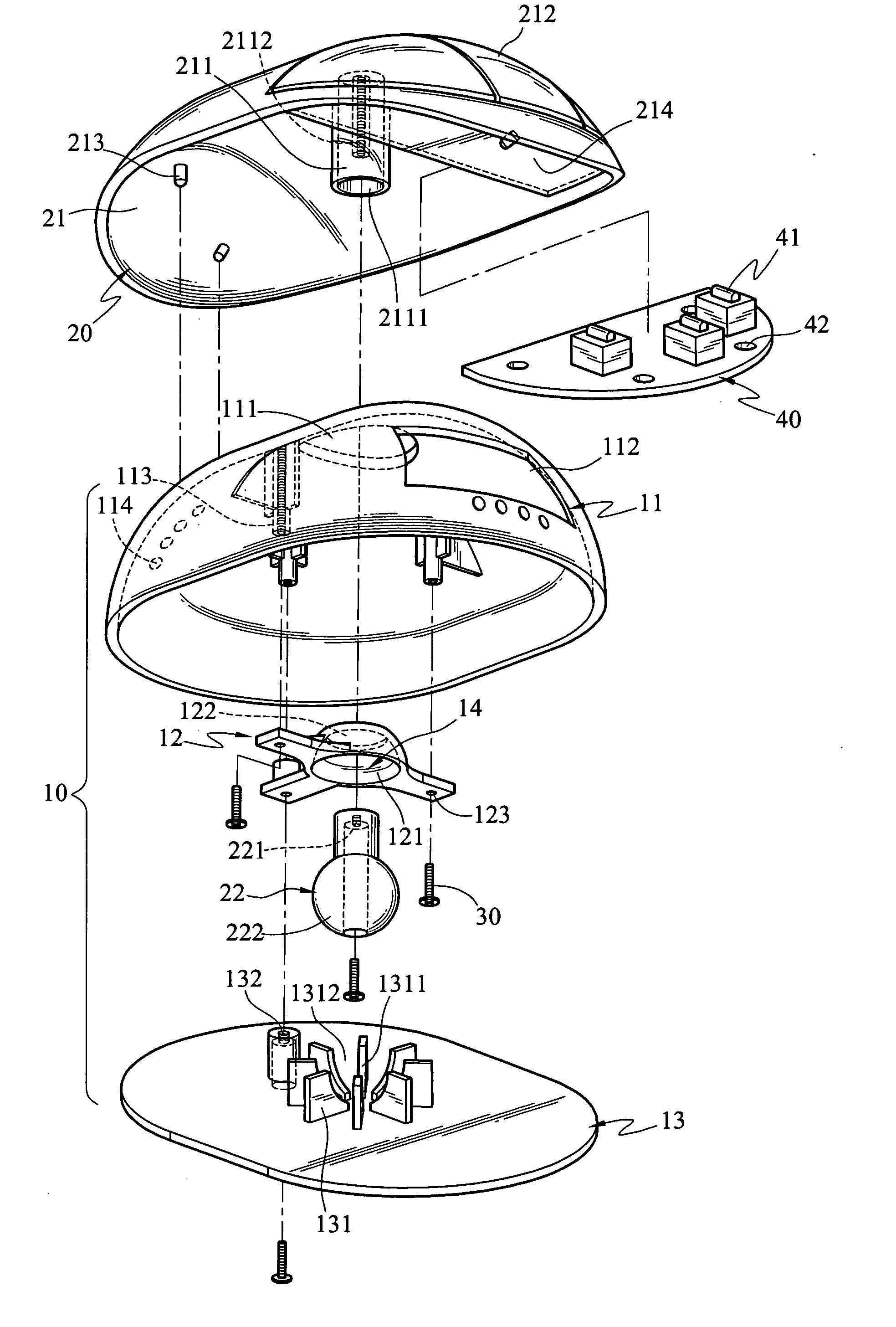
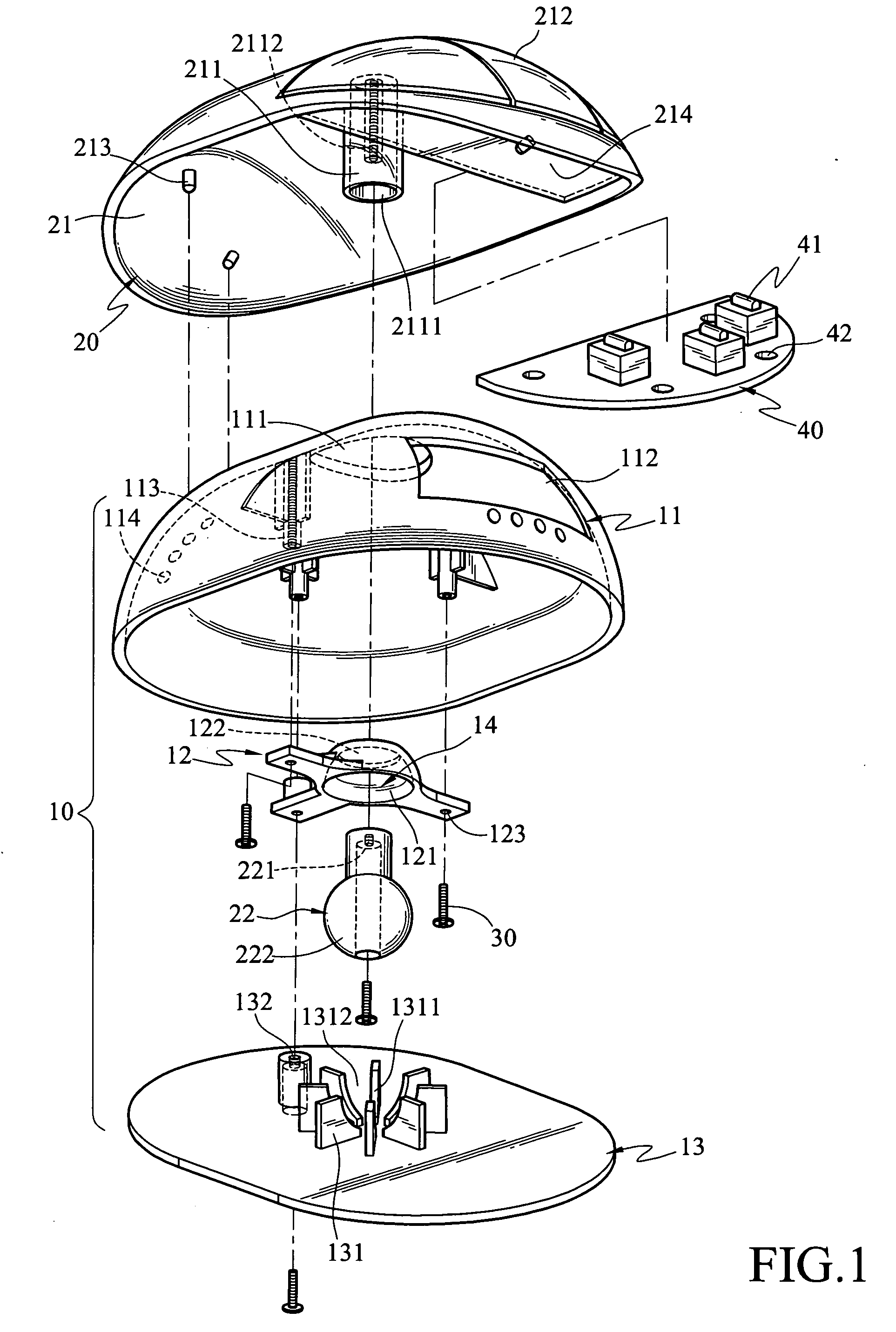
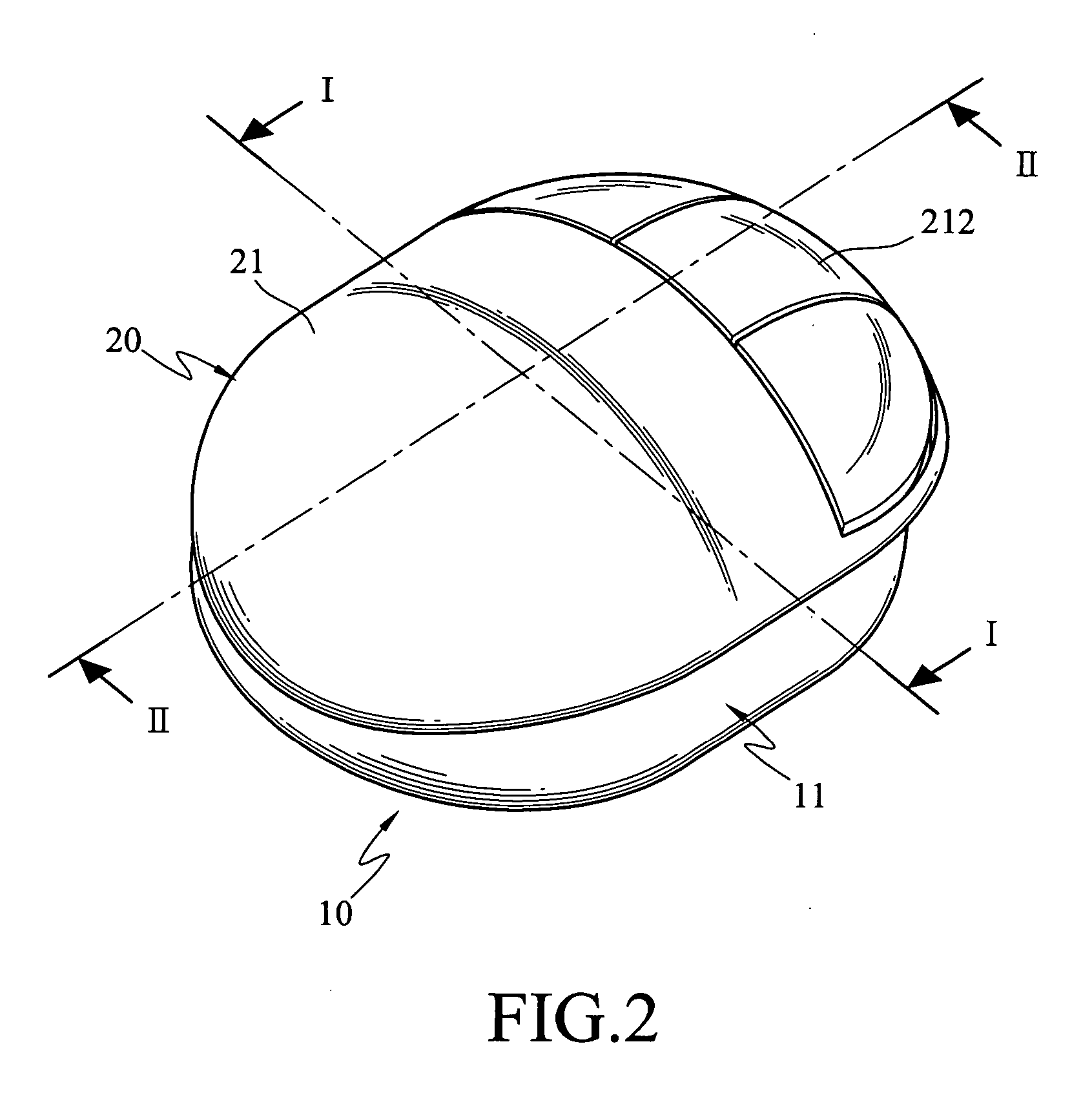
[0017] Refer to FIG. 1 for an exploded view of the invention, FIG. 2 for a perspective view of the invention, FIG. 3A for a cross-section taken on line I-I in FIG. 2, and FIG. 3B for a cross-section taken on line II-II in FIG. 2. The ergonomic mouse according to the invention includes a hollow body 10 and a sliding cap 20 that is slidable on the top of the hollow body 10 and can be anchored when reaching a desired operation position. Thus the sliding cap 20 may be fine-tuned and anchored on the hollow body 10, so that when the mouse is moved during operation the reaction force may be absorbed to avoid hurting the user's wrist and better meet ergonomic requirements.

[0018] The hollow body 10 includes a first shell 11, a retaining member 12 and a second shell 13.

[0019] The first shell 11 has a first port 111, a second port 112 and a trough 114 formed on the top, and a first screw hole 113 in the interior.

[0020] The retaining member 12 is coupled to the interior of the first shell 11...


PUM


Abstract

An ergonomic mouse has a sliding cap matching the curvature of a normal human palm. The sliding cap may be slid on the top of a hollow body to reach a desired operation position, then fine-tuned and anchored. Thus when the mouse is moved during operation, it can absorb reaction forces to avoid hurting the user's wrist and better meet ergonomic requirements.

Description

FIELD OF THE INVENTION [0001] The invention relates to an ergonomic mouse, and particularly to a mouse having a sliding cap pivotally mounted onto a hollow body and slidable thereon that may be fine-tuned and anchored to better meet ergonomic requirements. BACKGROUND OF THE INVENTION [0002] The typical mouse device has a track ball partially exposed on the outside. When the track ball rotates under a force, two wheels that are normal to each other located inside the mouse also rotate. Through optical detection, the rotation speeds of the two wheels are converted to moving distances on a set of coordinates. Hence when an electronic device is connected to the mouse, the cursor on the screen will move relatively from a start position to a destination position. [0003] In order to suit the operation type and computer usage habit of different users, the mouse design is constantly being improved. Nowadays a wide variety of mouse selections are available on the market. Each has its unique f...

Claims


Application Information

Patent Timeline
Patent Type & Authority Applications(United States)
IPC IPC(8): G09G5/08
CPCG06F3/03543G06F2203/0332G06F2203/0333
Inventor HOU, CHUAN-KUNGHSU, CHENG-HUA
Owner GUAN TECH
Why Eureka
Try Eureka