
High angular deflection micro-mirror system

a micro-mirror and high angular deflection technology, applied in the field of variable angle micro-mirrors, can solve the problems of limiting the angle of incidence and reflection angle affecting the manufacture of such a deformable mirror, and affecting the quality of the deformable mirror. , to achieve the effect of simple and economical manufacturing, large maximum angles of optical deflection

Inactive Publication Date: 2006-01-19
OPTRON SYST
View PDF30 Cites 37 Cited by
  • Summary
  • Abstract
  • Description
  • Claims
  • Application Information

AI Technical Summary

Benefits of technology

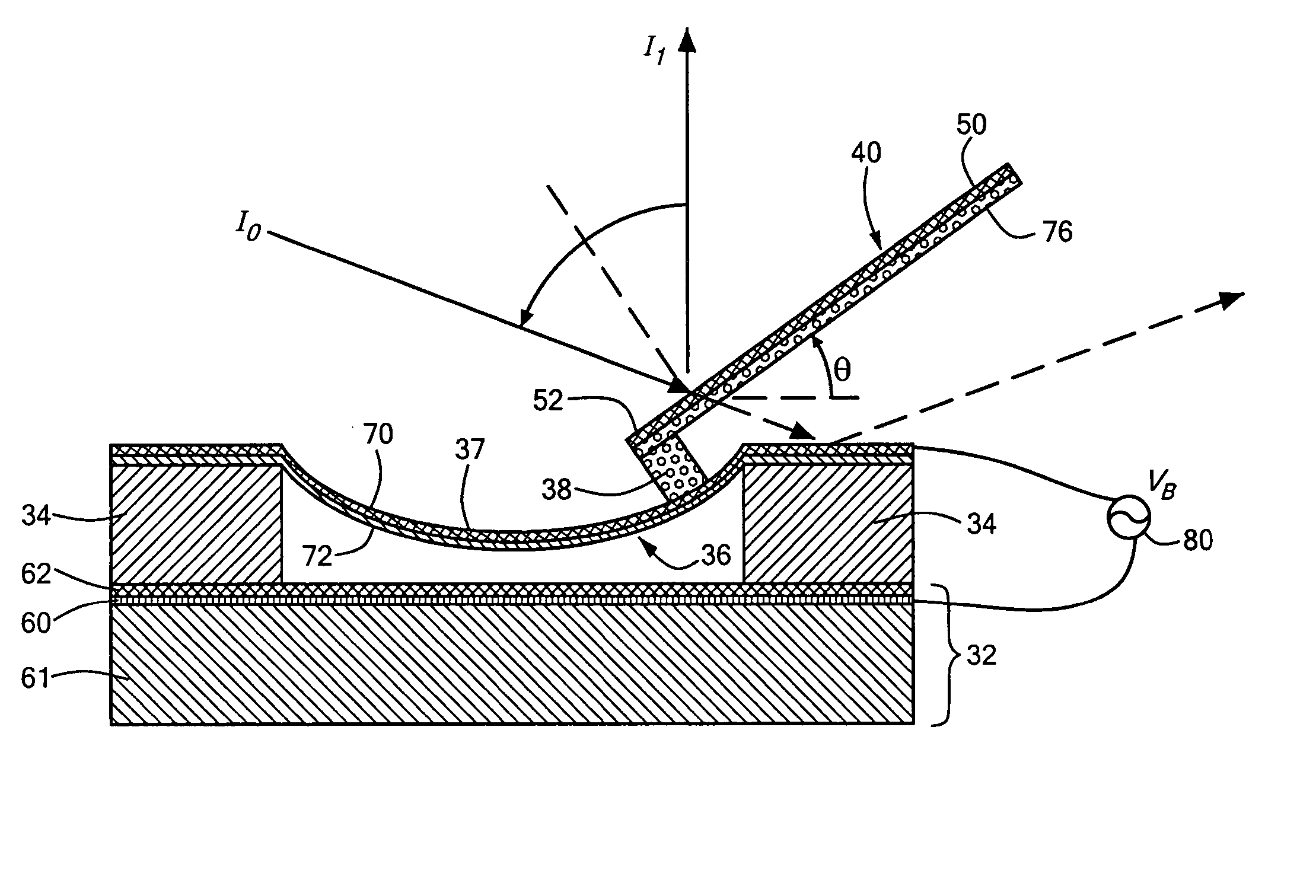
"This patent describes a new micro-mirror system that can direct light with high angular deflection. The system includes a substrate, a spacer structure, a deformable membrane, a rigid mirror, and a support. The deformable membrane is supported by the spacer structure and can be deflected to direct light. The system can be adjusted to achieve larger maximum angles of optical deflection and can be manufactured more easily and economically. The patent also describes an array of high angular deflection micro-mirrors that can be used in display applications."

Problems solved by technology

Manufacturing such a deformable mirror, however, is troublesome and controlling such a deformable mirror and preventing it from curling is also problematic.
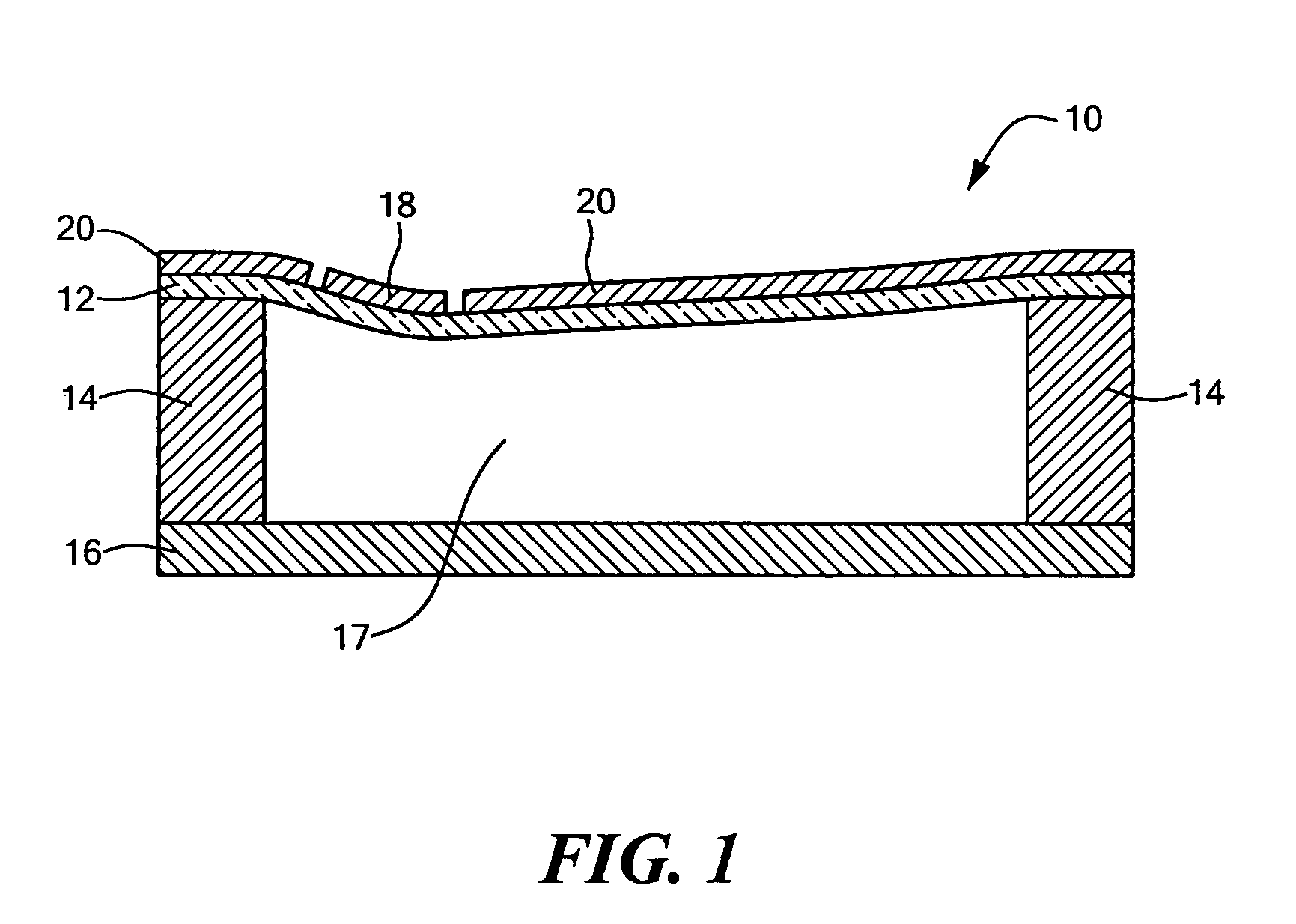
Moreover, when the membrane and the deformable mirror are deflected closer to the substrate, the deflection angle of the membrane limits the angle of incidence and the angle of reflection of the deformable mirror.
Also, once the membrane deforms to the extent that it contacts the substrate, no further adjustment of the deflection angle of the deformable mirror is possible, thus limiting the maximum deflection angle of the deformable mirror.

Method used


Image

  • High angular deflection micro-mirror system
  • High angular deflection micro-mirror system
  • High angular deflection micro-mirror system

Examples


Embodiment Construction

[0038] Referring to FIG. 1, as explained in the previous background section, a prior-art micro-mechanical membrane tilt mirror optical switch 10, includes a membrane 12 with an electrode 20 thereon. The membrane 12 is supported by dielectric spacers 14 above a substrate 16. A coated portion serves as a deformable mirror 18. As the membrane 12 deflects downward, as shown, the deformable mirror 18 deforms downward and thereby causes its associated reflection angle to enlarge.

[0039] Unfortunately, the use of the deformable mirror 18 results in several problems. These problems include the difficulty of manufacturing and controlling a deformable mirror in order to prevent it from curling when the membrane 12 deflects. Furthermore, because the deformable mirror 18 is layered into a cavity 17 between the spacers 14, the maximum angles of incidence and reflection of the deformable mirror are limited.

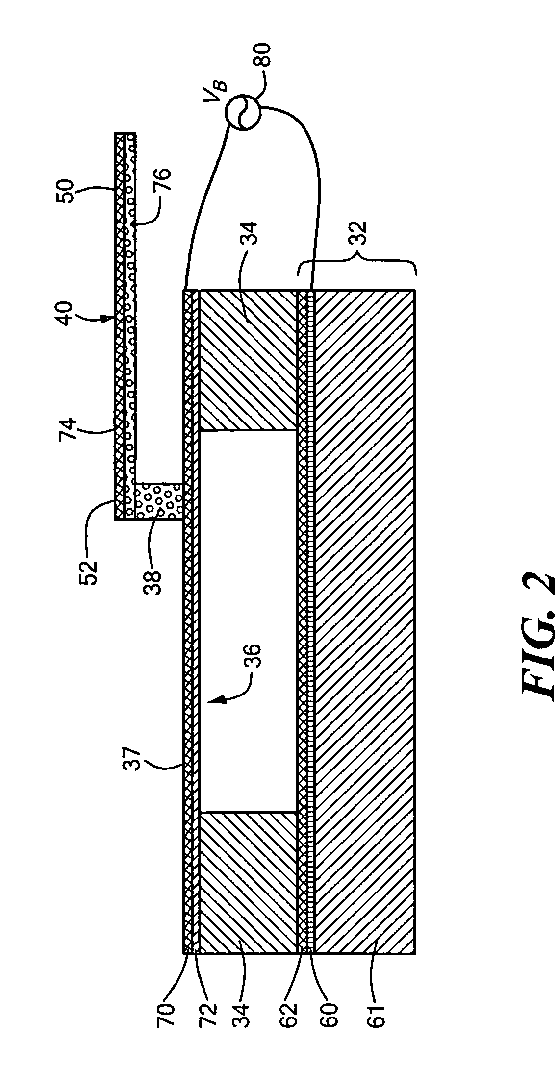
[0040] Referring to FIG. 2, in accordance with an embodiment of the invention, a high angu...


PUM


Abstract

A high angular deflection micro-mirror system including a substrate, a spacer structure extending from the substrate, a deformable membrane supported by the spacer structure, one or more supports located off center on the deformable membrane, and one or more mirrors on the support cantilevered therefrom to achieve a high angular deflection of the mirrors as the deformable membranes deform.

Description

FIELD OF THE INVENTION [0001] This invention relates to variable angle micro-mirrors used to steer (direct), attenuate, or deflect an optical beam. BACKGROUND OF THE INVENTION [0002] Mirrors (micro-mirrors), used to steer (direct), attenuate, or deflect an optical beam, are incorporated in many different devices including optical cross-connects. In U.S. Pat. No. 6,178,033, incorporated herein by this reference, a thin, deformable membrane with a deformable mirror thereon is supported above a substrate. When the deformable membrane is caused to deflect towards the substrate, the mirror deforms to steer (direct) an optical beam incident thereon. [0003] Manufacturing such a deformable mirror, however, is troublesome and controlling such a deformable mirror and preventing it from curling is also problematic. In fact, the '033 patent discusses the need for a bossed frame used to stiffen the membrane area surrounding the mirror. Moreover, when the membrane and the deformable mirror are de...

Claims


Application Information

Patent Timeline
Patent Type & Authority Applications(United States)
IPC IPC(8): G02B26/00
CPCG02B5/32G02B27/145G02B27/1026G02B26/0841
Inventor WU, XINGTAOWARDE, CARDINAL
Owner OPTRON SYST
Learn More