Apparatus and methods for handling shared services through virtual route forwarding(VRF) -aware- NAT

a technology of shared services and nat, applied in the direction of electrical apparatus, digital transmission, data switching networks, etc., can solve the problems of unwieldy implementation of nat by an enterprise having multiple sites, high cost, and insufficient number of ip addresses

Inactive Publication Date: 2006-01-19
CISCO TECH INC
View PDF15 Cites 185 Cited by
  • Summary
  • Abstract
  • Description
  • Claims
  • Application Information

AI Technical Summary

Benefits of technology

[0012] In accordance with various embodiments, the present invention is compatible with networks enhanced with Multi-Protocol Label Switching (MPLS) capabilities as defined in RFC 2547, entitled “BGP / MPLS VPNs,” by Rosen et al, March 1999, which is incorporated herein by reference for all purposes. Thus, the packet received includes an MPLS tag that includes a VPN identifier (or VRF table identifier). Thus, NAT may be accomplished, for example, through the use of a translation table that includes a VPN identifier in each table entry. In order to route the translated packet, the service provider network device maintains a plurality of routing tables (i.e., virtual route forwarding tables) that are associated with a plurality of VPNs. One of the routing tables is identified corresponding to a VPN or VRF table identifier present in the packet (e.g., MPLS tag) (which may also be stored in the translation table entry used to perform NAT). Once the routing table is identified, an entry in the routing table is identified using the IP source and destination addresses from the packet. The packet may then be routed using the identified routing table entry.

Problems solved by technology

With the explosion of the Internet, the number of IP addresses is not enough to give each computer a unique IP address.
In addition, since a NAT device is typically placed at each enterprise site, implementing NAT by an enterprise having multiple sites can be unwieldy, as well as costly.

Method used


Image

  • Apparatus and methods for handling shared services through virtual route forwarding(VRF) -aware- NAT
  • Apparatus and methods for handling shared services through virtual route forwarding(VRF) -aware- NAT
  • Apparatus and methods for handling shared services through virtual route forwarding(VRF) -aware- NAT

Examples


Embodiment Construction

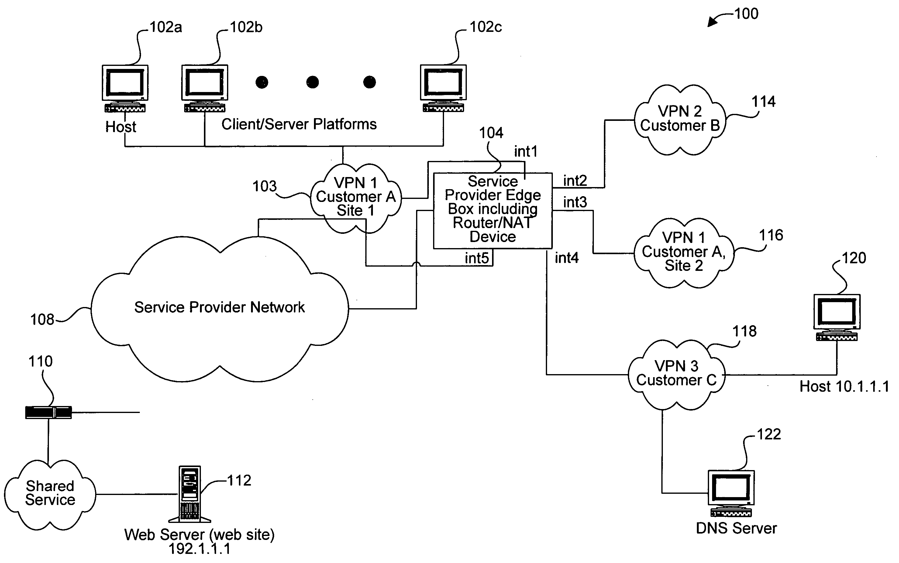
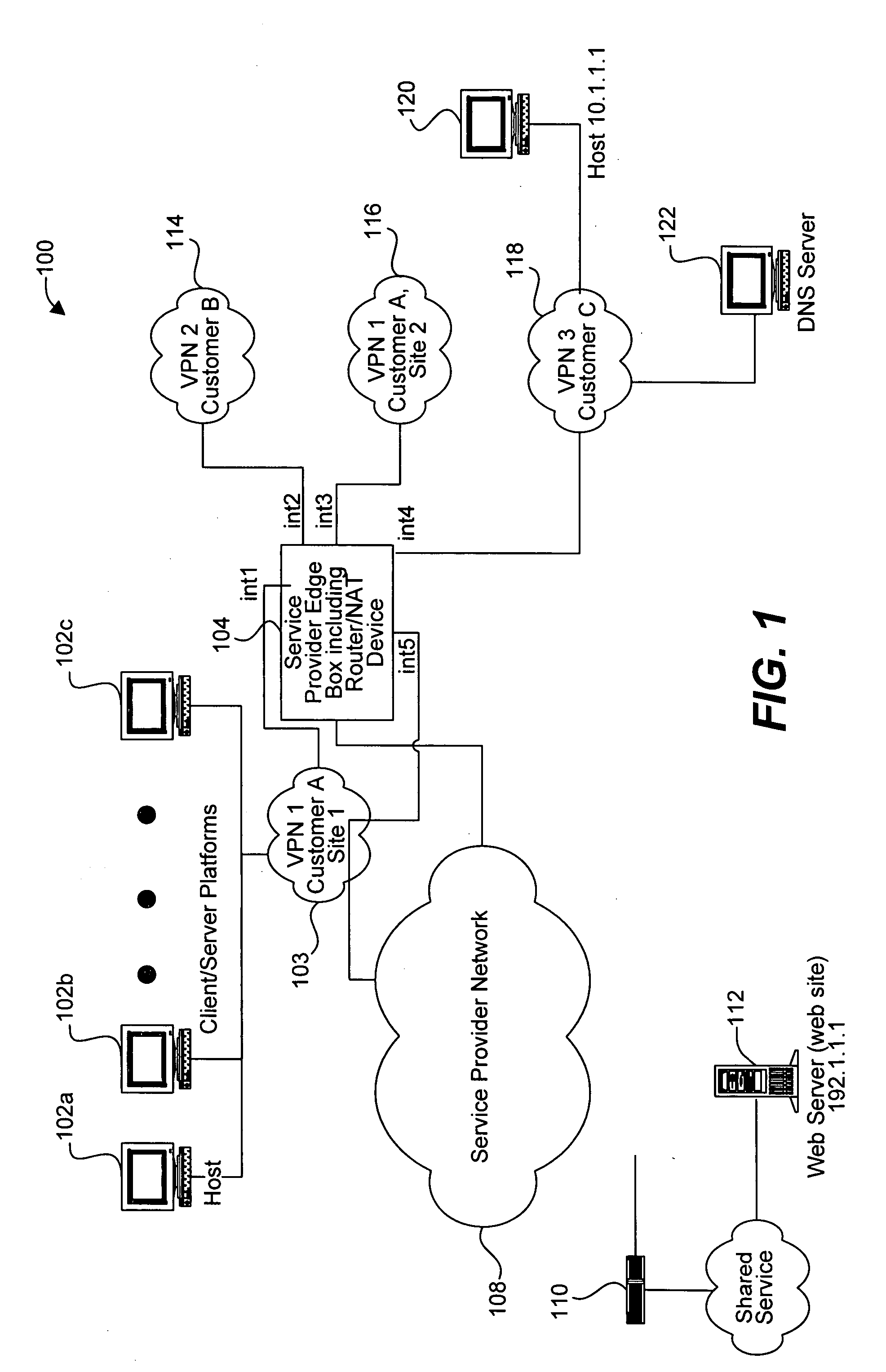
[0025] Reference will now be made in detail to a specific embodiment of the invention. An example of this embodiment is illustrated in the accompanying drawings. While the invention will be described in conjunction with this specific embodiment, it will be understood that it is not intended to limit the invention to one embodiment. On the contrary, it is intended to cover alternatives, modifications, and equivalents as may be included within the spirit and scope of the invention as defined by the appended claims. In the following description, numerous specific details are set forth in order to provide a thorough understanding of the present invention. The present invention may be practiced without some or all of these specific details. In other instances, well known process operations have not been described in detail in order not to unnecessarily obscure the present invention.

[0026] In the following description, various embodiments of the invention propose a solution to enable a p...


PUM


Abstract

Methods and apparatus for performing NAT are disclosed. Specifically, NAT is performed at a service provider network device associated with an interface of a service provider network. When a packet is sent from a VPN to a node outside the service provider network (e.g., to access a shared service), the packet includes a VPN identifier (or VRF identifier) In accordance with various embodiments, each packet includes an MPLS tag that includes the VPN identifier. The VPN identifier is stored in a translation table entry. The storing of the VPN identifier will enable a reply packet from the shared service network to the customer VPN to be routed using a routing table identified by the VPN identifier.

Description

BACKGROUND OF THE INVENTION [0001] The present invention relates to methods and apparatus for processing data within a computer network. More specifically, this invention relates to mechanisms for forwarding packets that either request or provide shared services that are available to a plurality of Virtual Private Networks (VPNs) via a service provider network. [0002] For a particular computer to communicate with other computers or web servers within a network (e.g., the Internet), the particular computer must have a unique IP address. IP protocol version 4 specifies 32 bits for the IP address, which theoretically gives about 4,294,967,296 unique IP addresses. However, there are actually only between 3.2 and 3.3 billion available IP addresses since the addresses are separated into classes and set aside for multicasting, testing and other special uses. With the explosion of the Internet, the number of IP addresses is not enough to give each computer a unique IP address. [0003] One so...

Claims


Application Information

Patent Timeline
Patent Type & Authority Applications(United States)
IPC IPC(8): H04L12/56H04L12/46H04L29/06H04L29/12
CPCH04L12/4675H04L29/12009H04L29/12462H04L29/12481H04L63/0272H04L45/50H04L45/54H04L61/255H04L61/2557H04L45/04H04L61/00
Inventor SOMASUNDARAM, MAHADEV
Owner CISCO TECH INC
Why Eureka
Try Eureka