Dedicated bandwidth data communication switch backplane

a data communication switch and backplane technology, applied in the field of data communication switching, can solve the problems of clock cycles, inefficient use of resources on the receive side of such backplanes, and congestion at the transmit side of such backplanes, and achieve the effect of reducing the congestion on the transmit sid

Inactive Publication Date: 2006-01-19
WSOU INVESTMENTS LLC
View PDF5 Cites 9 Cited by
  • Summary
  • Abstract
  • Description
  • Claims
  • Application Information

AI Technical Summary

Benefits of technology

[0004] In its most basic feature, the present invention reduces transmit side congestion in a LAN switch backplane through the expedient of a backplane matrix in which each controller has a dedicated packet bus for propagating packet data. Each bus has a root interfacing with the transmitting (root) controller and a plurality of leaves interfacing with receiving (le

Problems solved by technology

Regardless of whether one of these or some other ordering scheme is implemented, reliance on a shared bandwidth backplane, and its inherent requirement of regulating access in order to guarantee contention-free transmission, has led to congestion at the tran

Method used


Image

  • Dedicated bandwidth data communication switch backplane
  • Dedicated bandwidth data communication switch backplane
  • Dedicated bandwidth data communication switch backplane

Examples


Embodiment Construction

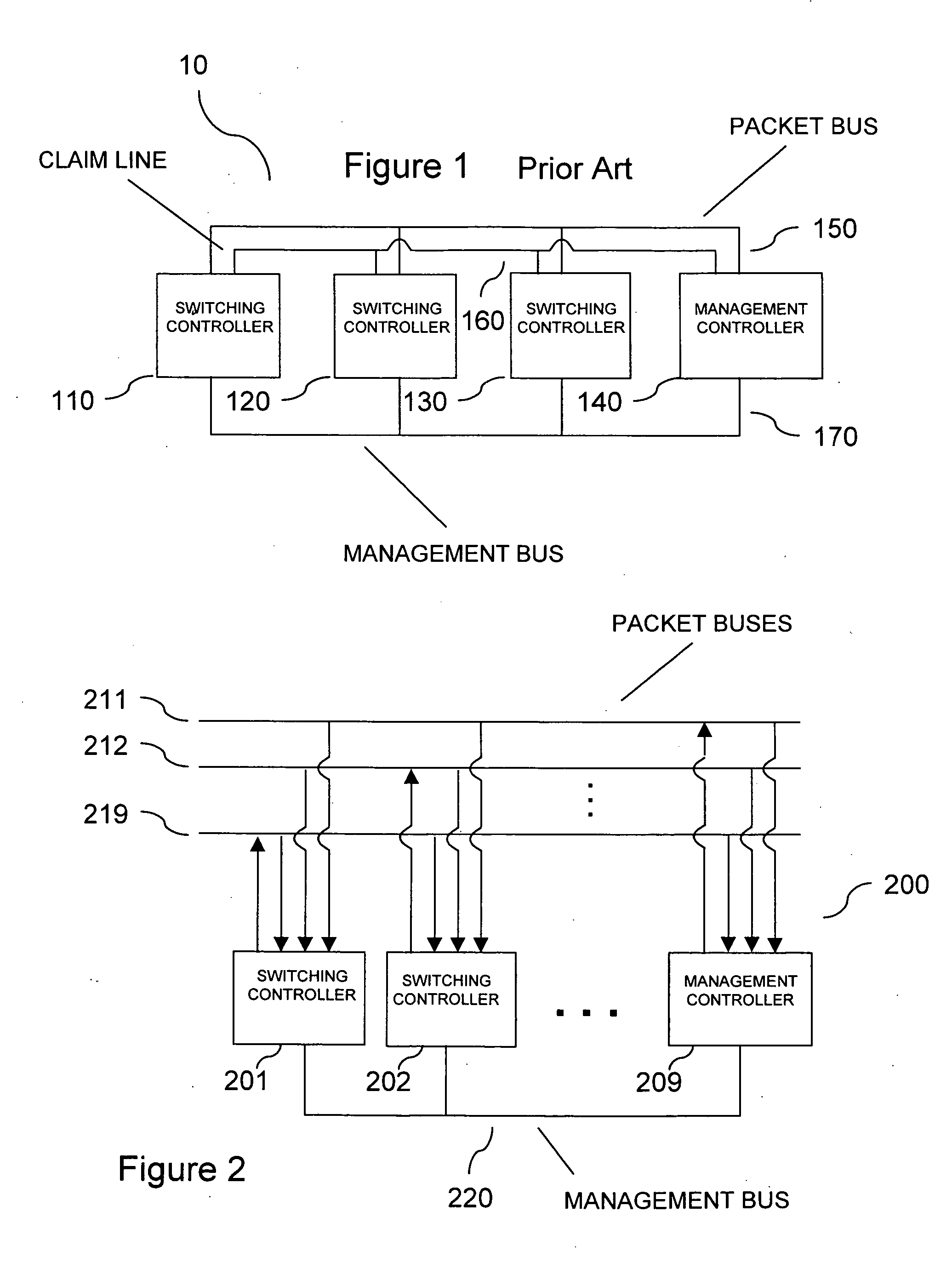
[0018] In FIG. 2, a LAN switching backplane 200 operative in accordance with the present invention is shown. Backplane 200 includes a matrix of packet buses 211-219 driven by controllers 201-209, respectively. Each bus has a root interfacing with the controller having the exclusive right to transmit packet data on the bus (i.e., the root controller) and leaves interfacing with the controllers receiving packet data off the bus (i.e., the leaf controllers). Preferably, each controller is the root controller on one of buses 211-219 and is a leaf controller on all buses 211-219, including the bus for which it is the root controller. Packets are preferably transmitted on buses 211-219 in a series of constant-bit data bursts at a rate of one burst per clock cycle. Buses 211-219 are broadcast-oriented such that all data bursts propagated on a bus reach all controllers 201-209. Thus, on any particular clock cycle, all controllers 201-209 may transmit a single data burst and may receive a pl...


PUM


Abstract

A LAN switch has a backplane matrix in which each controller has a dedicated packet bus for propagating packet data. Each bus has a root interfacing with the transmitting (root) controller and a plurality of leaves interfacing with receiving (leaf) controllers. This configuration enables each controller to simultaneously transmit packet data on the root of a bus and receive packet data off a plurality of leaves of other buses without contention. An efficient filtering and stalling system employed at the receive side of the backplane prevents the highly parallel traffic from causing receive side congestion.

Description

[0001] This is a continuation-in-part of application Ser. No. 09 / 063,493, filed Apr. 20, 1998, now pending.BACKGROUND OF THE INVENTION [0002] The present invention relates to data communication switching, and more particularly to local area network (LAN) switching. [0003] LAN switches interconnect network devices residing on different protocol domains. The switching functionality provided by LAN switches typically includes “local” switching between network devices on protocol domains interfacing with the same switching controller and “backplane” switching between network devices on protocol domains interfacing with different switching controllers. The backplanes used in LAN switch backplane switching have generally been configured as a packet bus shared by a plurality of controllers. A conventional LAN switch backplane is illustrated in FIG. 1. LAN switch backplane 10 includes switching controllers 110, 120, 130 and a management controller 140 taking turns transmitting packets over ...

Claims


Application Information

Patent Timeline
IPC IPC(8): H04L12/56H04L12/46
CPCH04L12/4641H04L49/354H04L49/351H04L45/7453
Inventor HAYWOOD, CHRISTOPHERSTONE, GEOFFREY C.
Owner WSOU INVESTMENTS LLC
Why Eureka
Try Eureka