Image display method and method for performing radiography of image

Inactive Publication Date: 2006-01-19
HITACHI MEDICAL CORP
View PDF1 Cites 3 Cited by
  • Summary
  • Abstract
  • Description
  • Claims
  • Application Information

AI Technical Summary

Benefits of technology

[0027] Another object of the present invention is to provide a method for displaying images that easily displays a

Problems solved by technology

This is because taking an image again in a precise examination of a region where a lesion is not observed in screening would constitute unnecessary radiation exposure.
Thus, there is a problem that in order to record a range for a precise examination in a memo pad, an operator must switch holding a mouse over to holding a pen several times.
Further, in screening, a mistake may occur when a operator transcribes a slice position of CT image where existence of a lesion is suspected into a memo pad.
There is also a possibility of a mistake occurring when setting slice positions for a precise examination based on the figures written into the memo pad.
Furthermore, in the conventional method using a memo pad, due to the complexity of the operations, a substantial time is required to set the scan conditions for changing from screening to precise examination.
During the time period taken to change from screening to precise examination, the subject to be examined is not allowed to move from the table to avoid inconformity of slice positions between screening and precise examination, whereby the time for setting the scan conditions of the precise examination is weariness for the subject.
There is a problem that recording these slice positions in a memo pad during the examination that requires speed is troublesome and complicated.
There also is a possibility that a mistake will be made when transcribing the positions of re-scanning in a memo pad or when setting the

Method used


Image

  • Image display method and method for performing radiography of image
  • Image display method and method for performing radiography of image
  • Image display method and method for performing radiography of image

Examples


Example

[0053] Hereinbelow, preferred embodiments of a method for displaying images and a method for performing radiography of image according to the present invention are described in reference of the attached drawings.

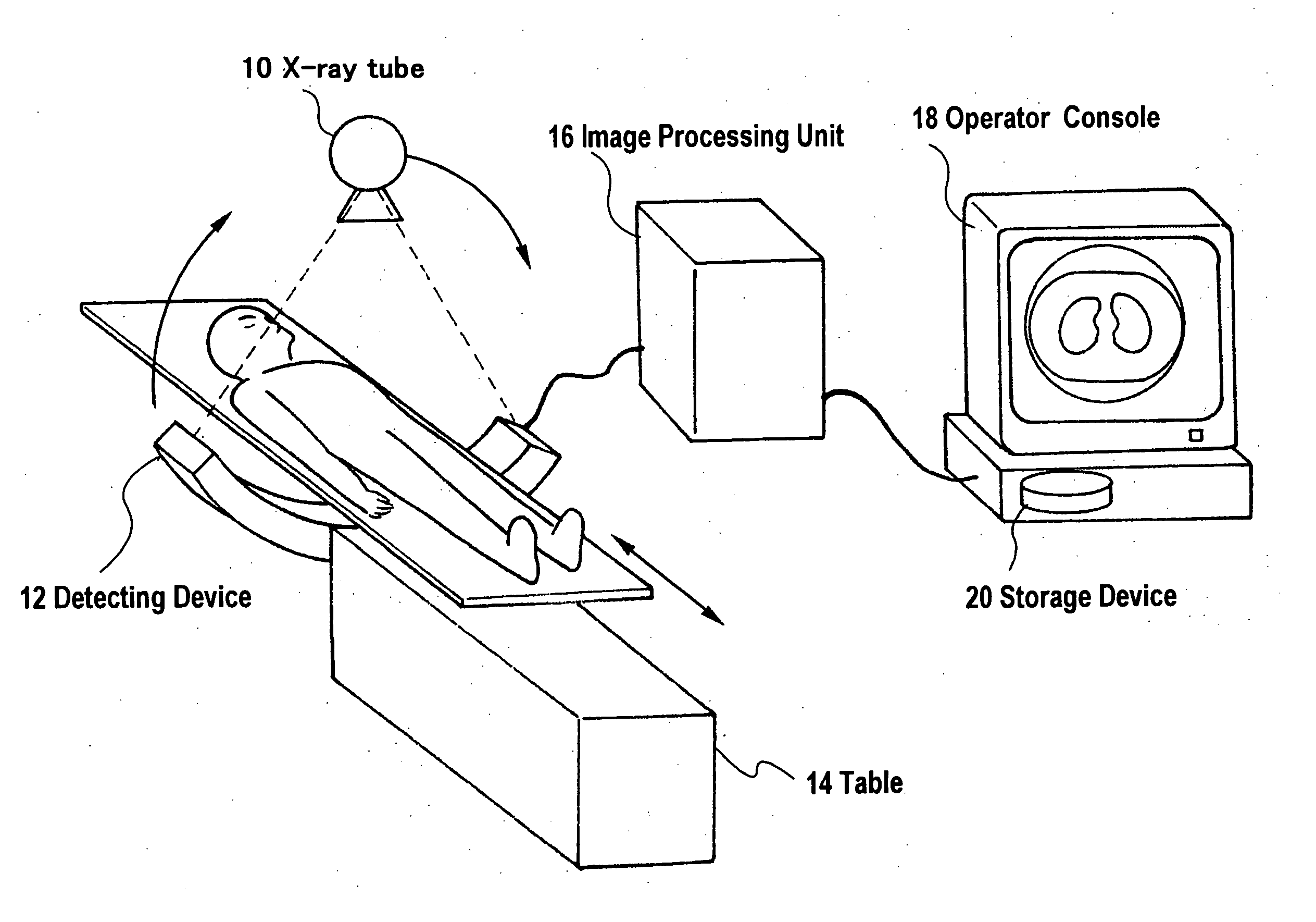
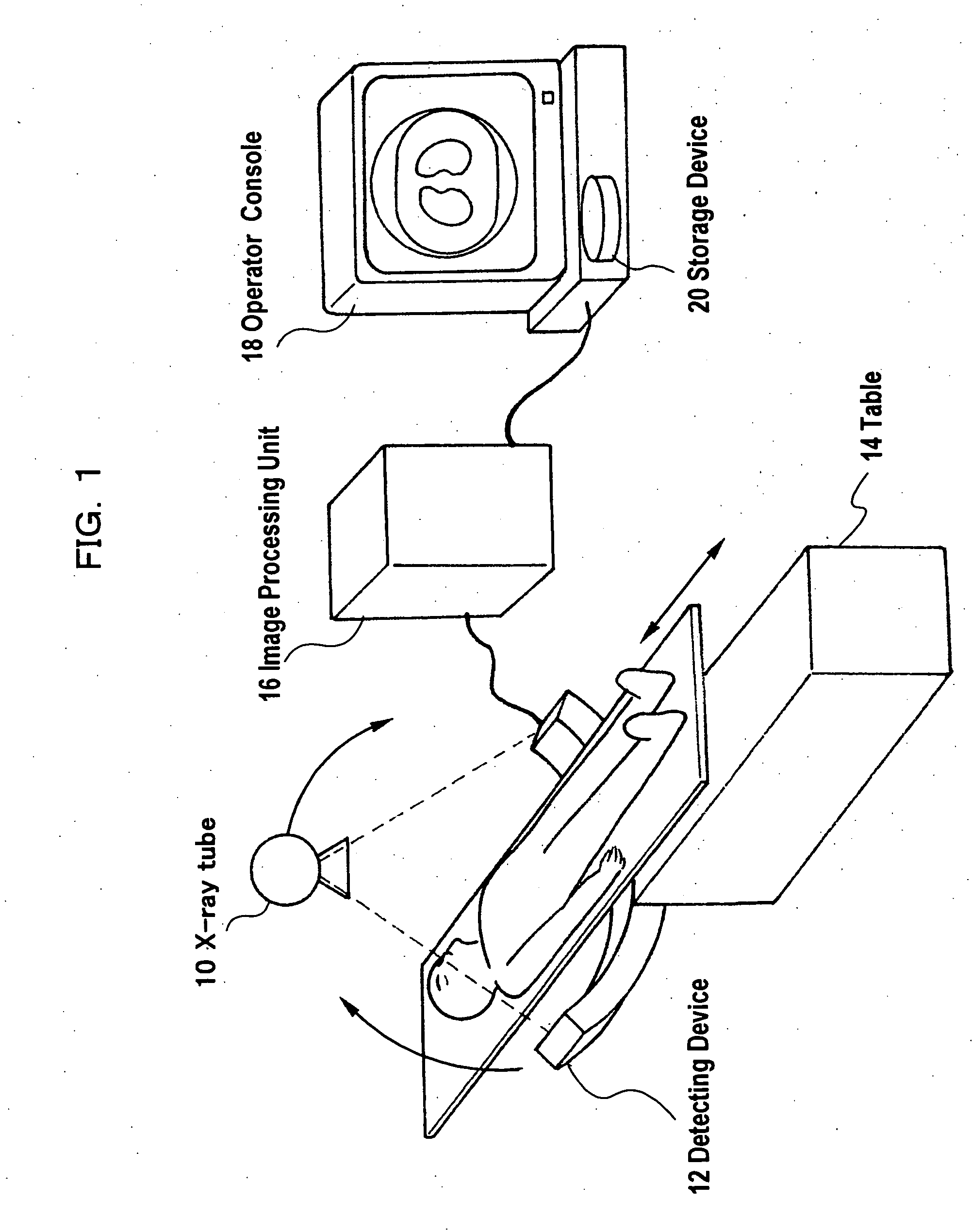
[0054]FIG. 1 is a schematic diagram showing a hardware configuration of an X-ray CT apparatus to which the method for displaying images and method for performing radiography of image according to the present invention are applied.

[0055] As shown in FIG. 1, the X-ray CT apparatus includes an X-ray tube 10, a detecting device 12, a table 14, an image processing unit 16 and an operator console 18.

[0056] The X-ray tube 10 and the detecting device 12 are disposed so as to face each other, and when taking a tomogram (CT image) they revolve around the circumference of the table 14 on which a subject is positioned. X-rays radiated from the X-ray tube 10 penetrate through the subject and the table, and are detected by the detecting device 12. Signals detected by the detecting devi...


PUM


Abstract

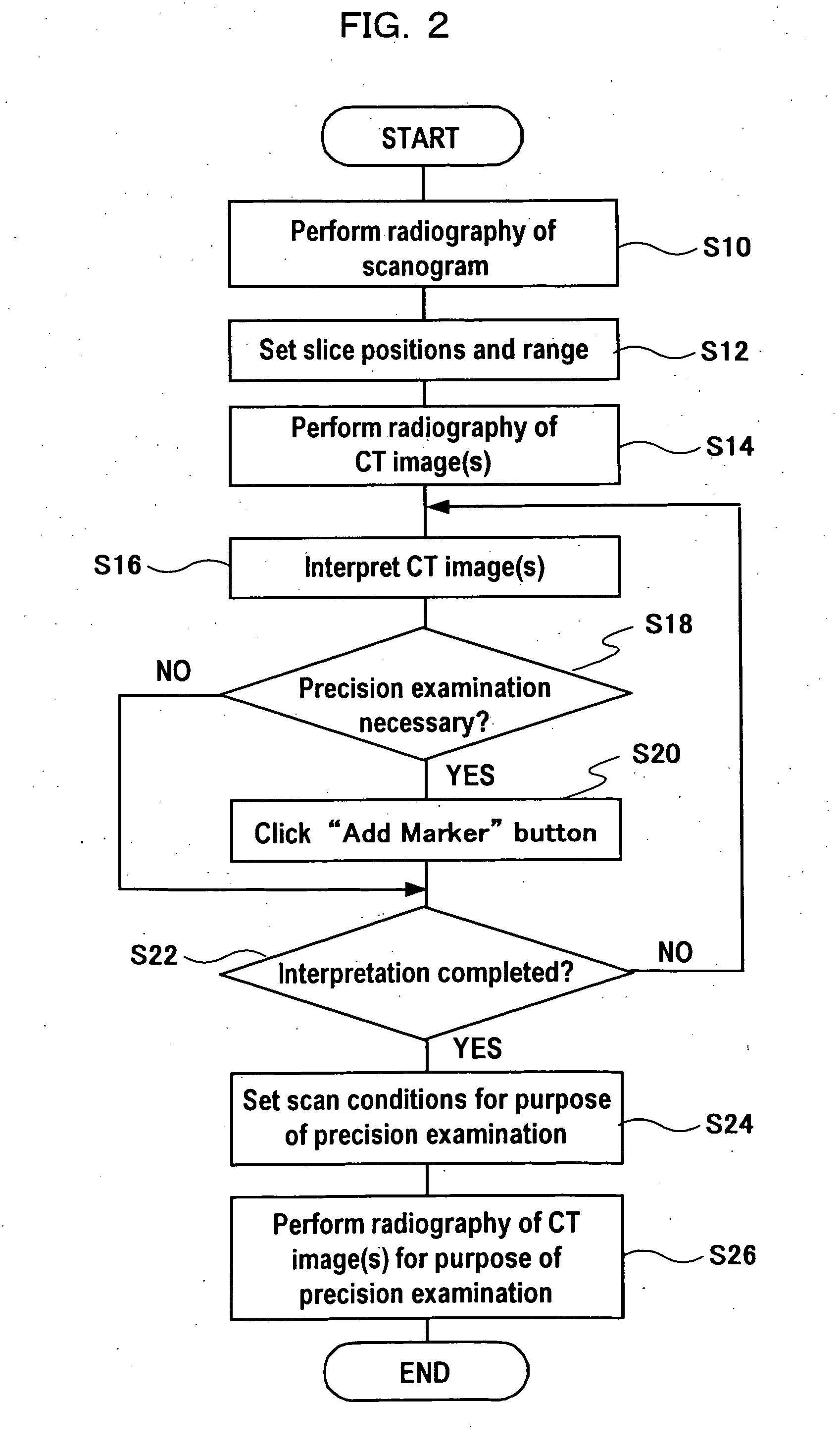
CT images are interpreted while being displayed in order (STEP S16), and when a CT image is observed in which the presence of a lesion is suspected, an “Add Marker” button is clicked to add a marker to that CT image (STEPS S18, S20). By means of the click operation, a marker is automatically added at a slice position on a scanogram that corresponds to the CT image (CT image requiring precise examination) in which the presence of a lesion is suspected. By automatically adding a marker at a desired slice position on a scanogram in this manner, it is possible to set scanning conditions for the purpose of a precise examination while viewing the marker on the scanogram (STEP S24). It is thus possible to accurately set a range for precise examination by a simple operation in a short time.

Description

TECHNICAL FIELD [0001] The present invention relates to a method for displaying images and a method for performing radiography of image, and more particularly to a method for displaying images and a method for performing radiography of image that can simply carry out instructions concerning a tomogram of a subject in doing a precise examination or rescan. BACKGROUND ART [0002] (1) Method of Setting a Range for Precise Examination in CT (Computed Tomography) Examination [0003] In a CT examination, a scanogram is taken first, and slice positions and a range are subsequently determined based on the scanogram before taking CT images. Next, screening (assessment of the presence or absence of a lesion) is performed using the CT images to perform a precise examination. Hereinbelow, the term “precise examination” refers to an examination that is performed in a CT examination with the purpose of observing a lesion when the presence of a lesion is suspected based on the results of screening. ...

Claims


Application Information

Patent Timeline
IPC IPC(8): G06K9/00G16H30/40
CPCA61B6/032G06F19/321A61B6/488G16H30/40
Inventor FUKUZAWA, KAORI
Owner HITACHI MEDICAL CORP
Why Eureka
Try Eureka