Communications connector with flexible printed circuit board

a communication connector and printed circuit board technology, applied in the direction of printed circuit aspects, coupling device details, coupling device connection, etc., can solve the problems of increasing problems such as capacitive and inductive coupling between closely spaced parallel conductors within the jack and/or plug

Active Publication Date: 2006-01-19
PANDUIT
View PDF57 Cites 137 Cited by
  • Summary
  • Abstract
  • Description
  • Claims
  • Application Information

AI Technical Summary

Problems solved by technology

In the communications industry, as data transmission rates have steadily increased, crosstalk due to capacitive and induct

Method used


Image

  • Communications connector with flexible printed circuit board
  • Communications connector with flexible printed circuit board
  • Communications connector with flexible printed circuit board

Examples


Embodiment Construction

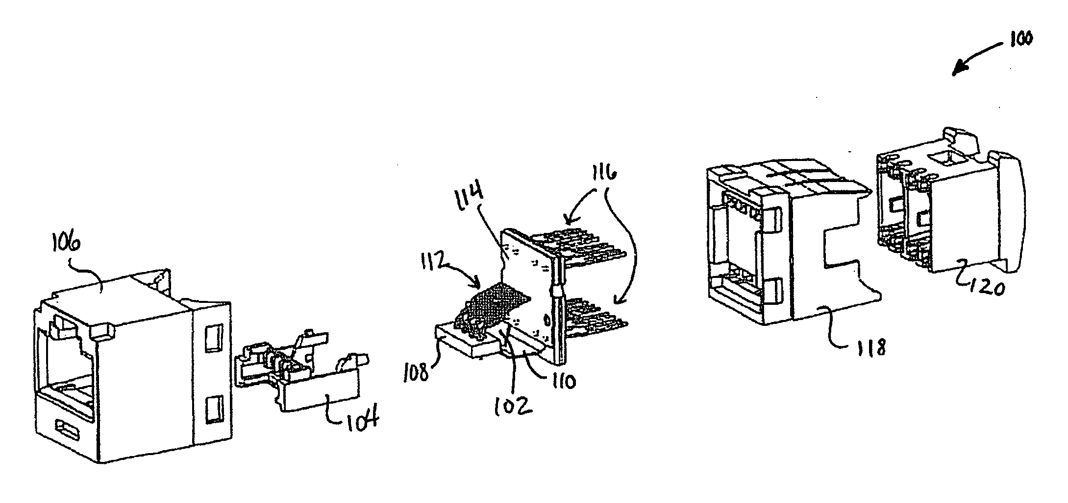
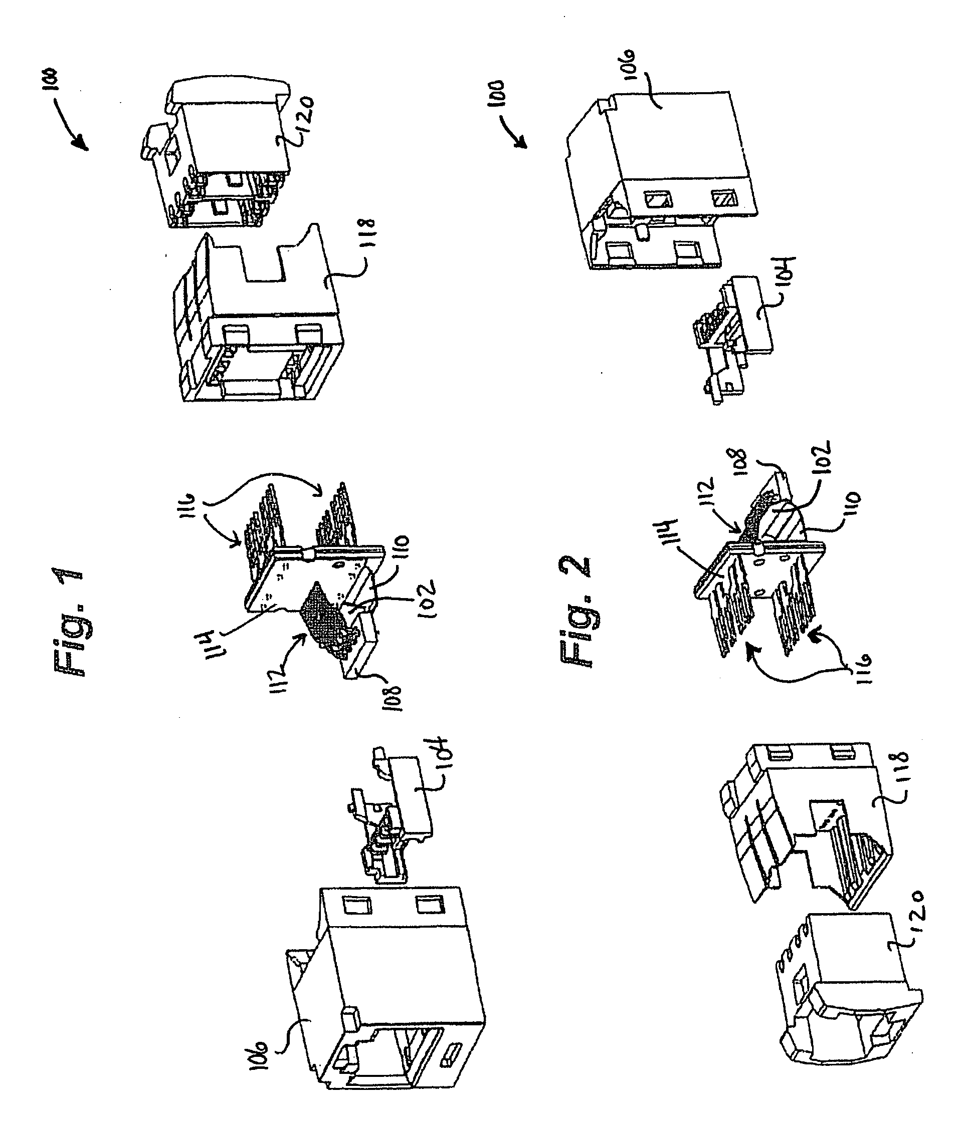
[0005]FIG. 1 is a front exploded perspective view of a communications jack

[0006]FIG. 2 is a rear exploded perspective view of a communications jack;

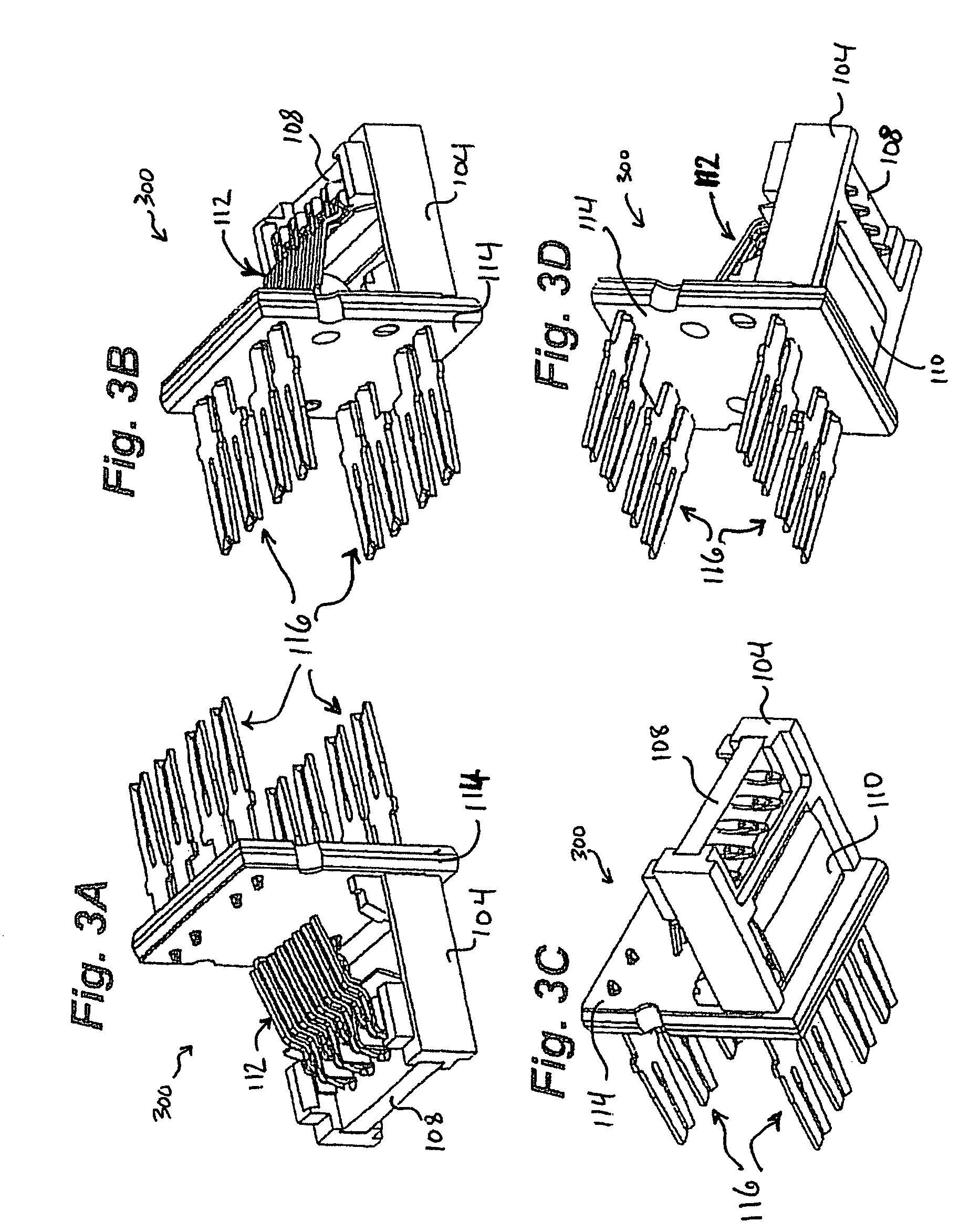
[0007]FIGS. 3A-3D are different perspective views of an assembly composing an internal portion of the communications jack of FIGS. 1 and 2;

[0008]FIG. 4 is a perspective view of an assembly composing an internal portion of the communications jack of FIG. 1;

[0009]FIG. 5 is a side cross-sectional view of the communications jack of FIG. 1;

[0010]FIG. 6 is a side cross-sectional view of an embodiment of the communications jack of FIG. 1;

[0011]FIG. 7A illustrates a design of a Flexible Printed Circuit for leads 3, 4, 5, and 6 for a Printed Circuit Board in a communications jack;

[0012]FIG. 7B illustrates a design of a Flexible Printed Circuit for lead 3 for a Printed Circuit Board in a communications jack;

[0013]FIG. 7C illustrates a design of a Flexible Printed Circuit for lead 4 for a Printed Circuit Board in a communications jack;

[001...


PUM


Abstract

A communications connector with a flexible printed circuit board is provided. The flexible printed circuit board is electronically and mechanically connected to the plug interface contacts of the jack near the plug/jack interface, in order to provide effective crosstalk compensation. The flexible printed circuit board has fingers at one end allowing it to flex as individual plug interface contacts are depressed when a plug is installed into the jack. A second end of the flexible printed circuit board has through holes for accepting insulation displacement contacts. The second end of the flexible printed circuit board may be rigidly supported, to allow insertion of the insulation displacement contacts. Various designs for capacitive and/or inductive couplings are provided, resulting in improved crosstalk performance.

Description

CROSS-REFERENCE TO RELATED APPLICATIONS [0001] This application claims the benefit of U.S. Provisional Application No. 60 / 587,416, filed Jul. 13, 2004, and U.S. Provisional Application No. 60 / 637,024, filed Dec. 17, 2004. The entireties of each of these applications are hereby incorporated by reference herein.FIELD OF THE INVENTION [0002] The present invention relates generally to electrical connectors, and more particularly, to a modular communication jack having a flexible printed circuit board. BACKGROUND OF THE INVENTION [0003] In the communications industry, as data transmission rates have steadily increased, crosstalk due to capacitive and inductive couplings among the closely spaced parallel conductors within the jack and / or plug has become increasingly problematic. Modular connectors with improved crosstalk performance have been designed to meet the increasingly demanding standards. Many of these improved connectors have included concepts disclosed in U.S. Pat. No. 5,997,358...

Claims


Application Information

Patent Timeline
IPC IPC(8): H01R29/00H01R24/00
CPCH01R13/6658H05K1/0228H05K1/189H01R13/6467H01R13/6461H01R24/64H05K2201/10189
Inventor CAVENEY, JACK E.
Owner PANDUIT
Why Eureka
Try Eureka