Ceramic diverter for tub spout

a diverter valve and ceramic technology, applied in the field of ceramic diverter valves for tub spouts, can solve the problems of small amount of water flowing out of the valve, valve seals that cannot be completely sealed off, and small amount of water leakage through the valve and valve seal

Inactive Publication Date: 2006-01-26
XIAMEN LOTA INT CO LTD
View PDF18 Cites 25 Cited by
  • Summary
  • Abstract
  • Description
  • Claims
  • Application Information

AI Technical Summary

Benefits of technology

The patent text describes a device that prevents water from flowing out of a tub spout when the orifices of two ceramic discs are not aligned. Instead, the water is diverted to a shower head. The technical effect of this device is to improve the efficiency and accuracy of water flow control in a shower system.

Problems solved by technology

The technical problem addressed in this patent text is the inefficient and wasteful use of water in small bathrooms where there is no separate shower stall. The prior art stem-type diverter valves used to divert water from the tub spout to the shower head do not completely seal off the flow of water, resulting in some water leaking through the valve and discharging out of the tub spout. The patent seeks to provide a diverter valve that completely seals off the flow of water through the tub spout to address this problem.

Method used


Image

  • Ceramic diverter for tub spout
  • Ceramic diverter for tub spout
  • Ceramic diverter for tub spout

Examples


Embodiment Construction

[0030] This invention may be made in many different forms. The following drawings and description describe a preferred embodiment of the invention. It will be understood that the description is to be considered as but one example of the principles of the invention. The description is not intended to limit the broadest aspect of the invention to the illustrated embodiment.

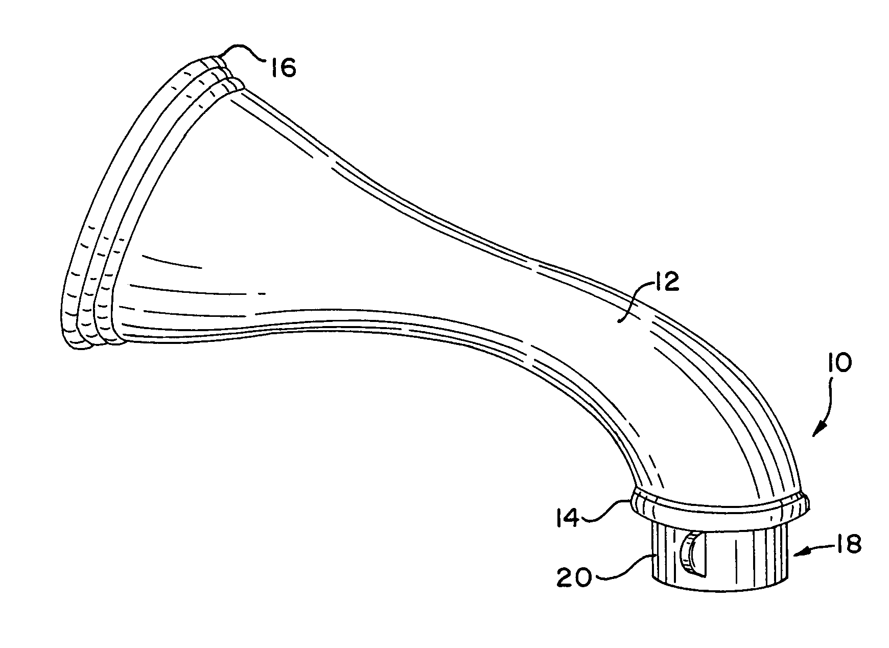
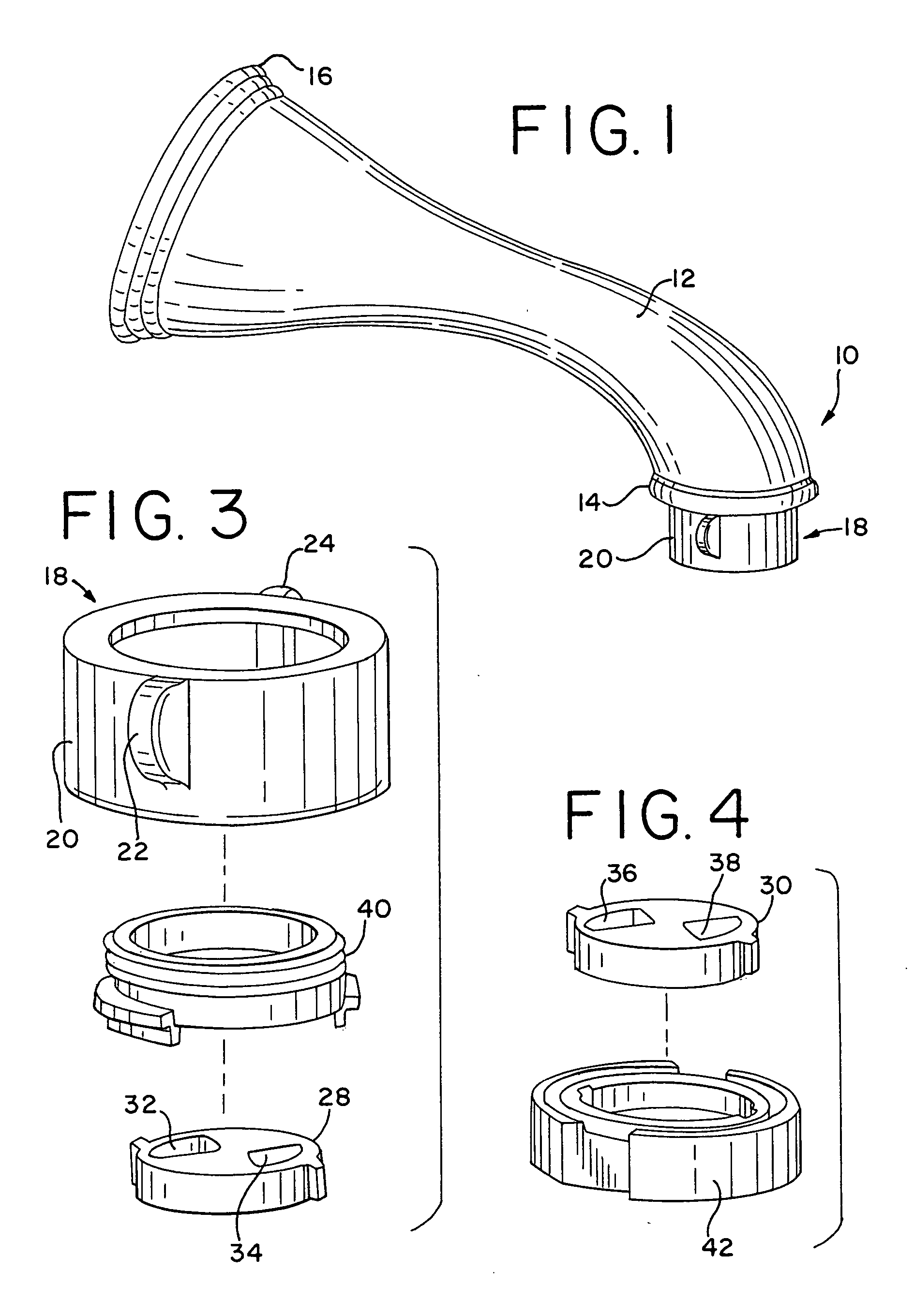
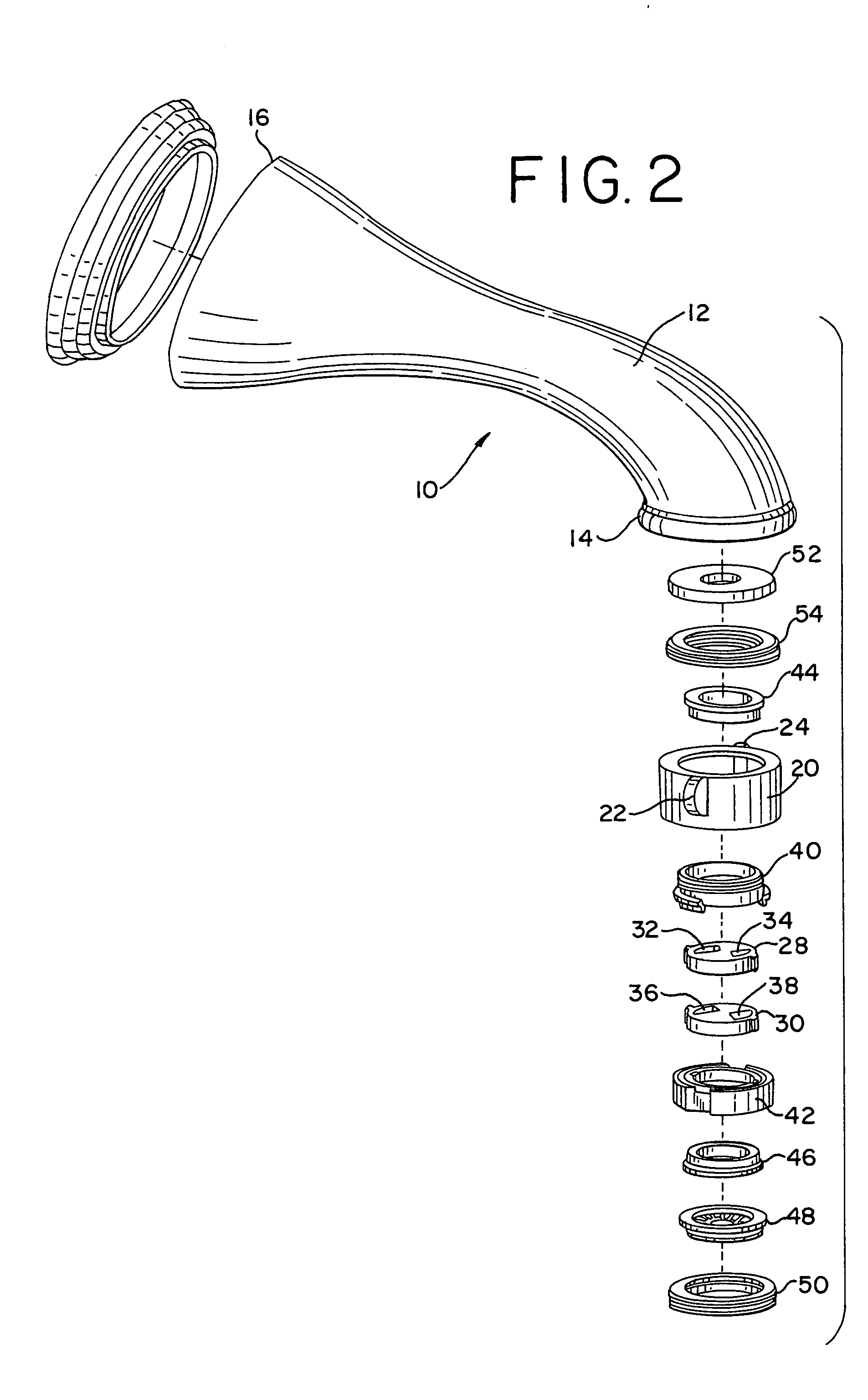
[0031] As may be seen in FIG. 1, the invention is a water diverter 10. In this embodiment shown in FIG. 1, the water diverter 10 includes a tub spout 12. The tub spout has an outlet port 14. The outlet port 14 is the distal end of the tub spout 12 from which water passing through the tub spout 12 is discharged into the tub. The tub spout 12 also has an inlet port 16. The inlet port 16 is at the opposite distal end of the tub spout 12, and is the point at which municipal or other supply water enters the tub spout 12.

[0032] In one aspect of the invention, the water diverter 10 may comprise, in combination, the tub s...


PUM


Abstract

A water diverter comprising, in combination, a tub spout having an inlet port and an outlet port. The device further includes a cartridge for installation at the outlet port of the tub spout. The cartridge includes a first ceramic disc with orifices, and a second ceramic disc with orifices. The first and second ceramic discs are rotatable relative to each other. Particularly, the discs are movable between a first position in which their respective orifices are substantially aligned to permit flow of the water to the outlet port of the tub spout, and a second position in which their orifices are substantially non-aligned to prevent the flow of the water to the outlet port of the tub spout, and instead divert the flow of water to a showerhead.

Description


Claims


Application Information

Patent Timeline
Owner XIAMEN LOTA INT CO LTD
Why Eureka
Try Eureka