Cam actuated drum brake

a drum brake and cam technology, applied in the field of brakes, can solve the problems of significant cost to vehicle fleet operators, wear and deterioration of the brake lining, and achieve the effect of sufficient actuation force, thicker brake lining, and increased travel of the brake sho

Active Publication Date: 2006-01-26
BENDIKS SPAJSER FAUNDEJSHN BREJK LLK
View PDF6 Cites 17 Cited by
  • Summary
  • Abstract
  • Description
  • Claims
  • Application Information

AI Technical Summary

Benefits of technology

[0007] The present invention provides a brake and several improved brake components. In particular, the present invention provides an improved cam that enables increased travel of brake shoes and th

Problems solved by technology

The brake linings are subject to wear and deterioration.
Replacement of the linings is a significant cost to vehicle fleet opera

Method used


Image

  • Cam actuated drum brake
  • Cam actuated drum brake
  • Cam actuated drum brake

Examples


Embodiment Construction

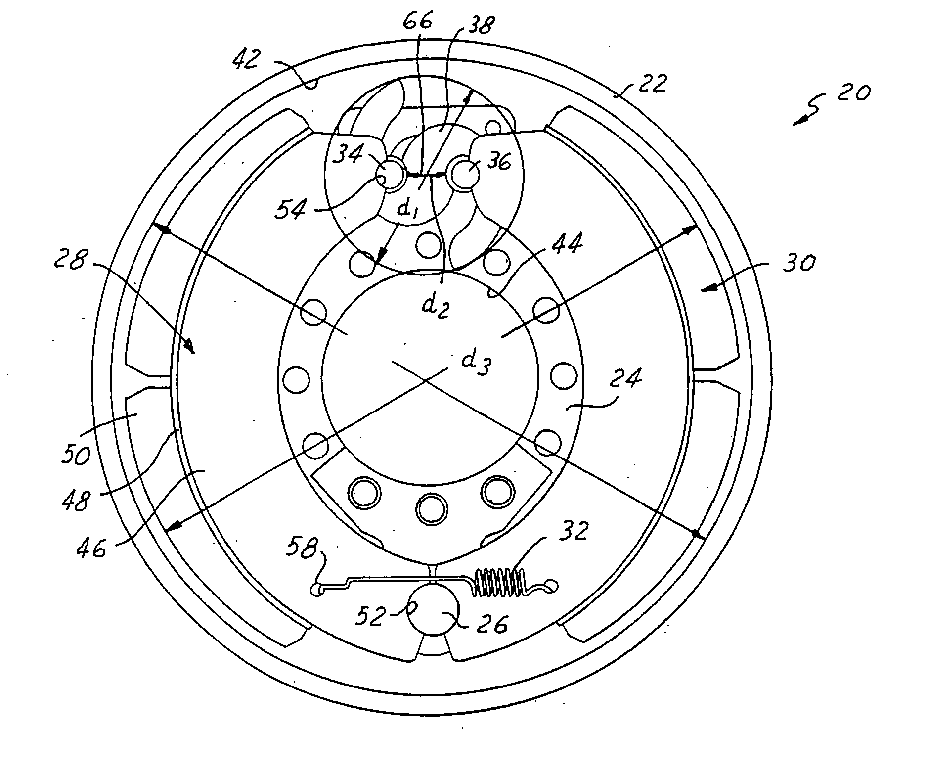
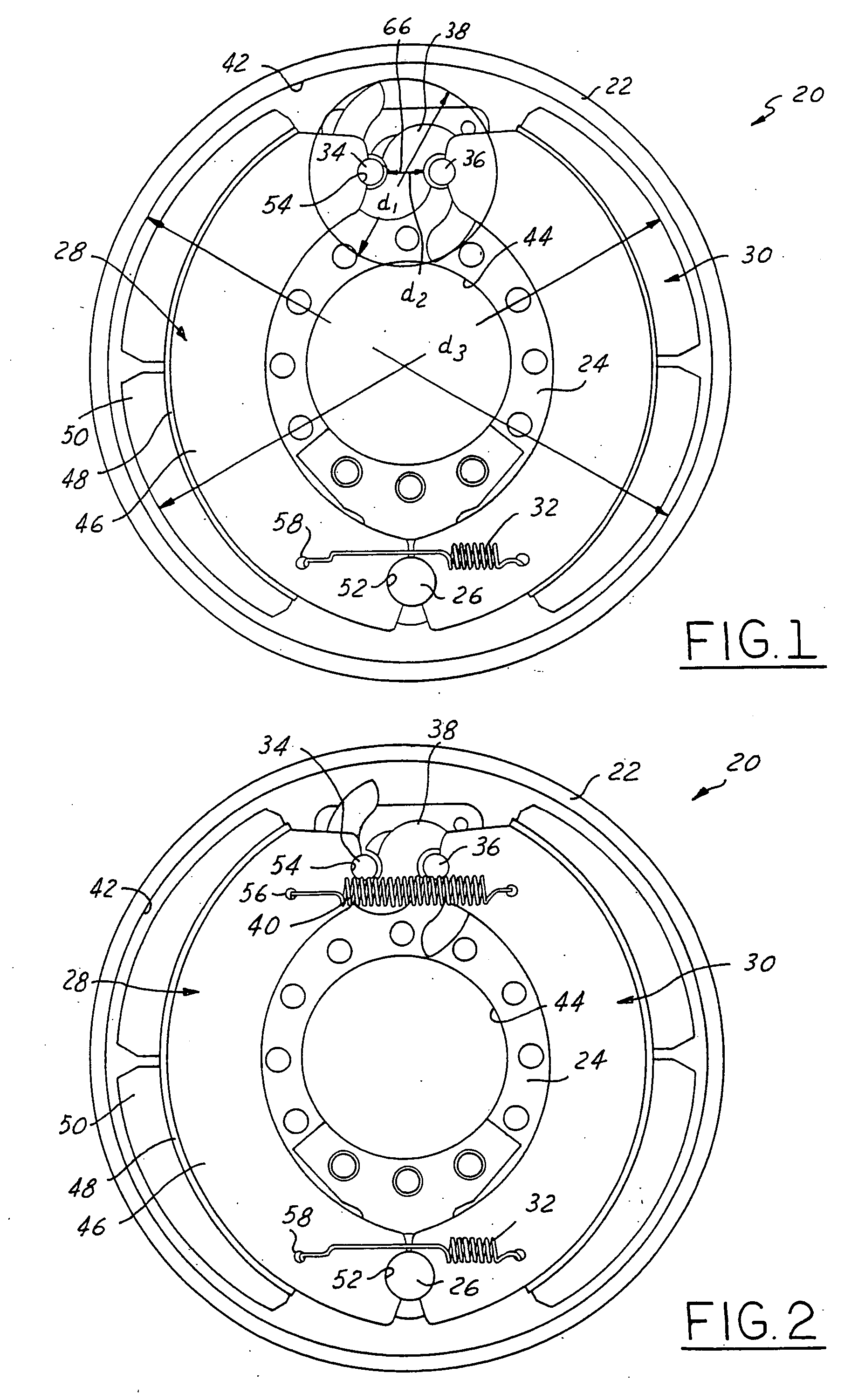
[0022] Referring now to the drawings wherein like reference numerals are used to identify identical components in the various views, FIGS. 1-2 illustrate a brake 20 in accordance with one embodiment of the present invention. Brake 20 is particularly adapted for use in heavy trucks. It should be understood, however, that brake 20 may be used on a wide variety of vehicles and in non-vehicular applications. Brake 20 may include a brake drum 22, a brake spider 24, an anchor 26, brake shoes 28, 30, retainer springs 32, cam followers 34, 36, a cam 38 in accordance with the present invention, and return springs 40.

[0023] Drum 22 provides a braking surface 42 and is conventional in the art. Drum 22 may be made from conventional metals and metal alloys such as steel. Drum 22 is annular and rotates with the vehicle wheel or wheels at one end of an axle.

[0024] Brake spider 24 is provided to mount the various components of brake 20 and is also conventional in the art. Spider 24 defines a cent...


PUM


Abstract

A cam for a brake is provided that allows for greater brake shoe travel and thicker brake linings while providing the same or greater mechanical force as compared to conventional cams. One or more lobes of the cam include multiple portions having varying profiles in axial cross-section. The variation in the cam profiles results in a cam in which the outermost ends or tips of the lobes are longer than in conventional cams yet retain the same mechanical strength.

Description

BACKGROUND OF THE INVENTION [0001] 1. Field of the Invention [0002] This invention relates to brakes and, in particular, to a cam actuated drum brake that enables the use of brake linings having increased thickness as compared to conventional brakes. [0003] 2. Discussion of Related Art [0004] A conventional drum brake includes a brake drum that rotates with a wheel or wheels proximate one end of an axle. The brake drum defines a radially inner braking surface. A brake spider is disposed about the axle and supports an anchor pin that extends axially from the spider. A pair of brake shoes are pivotally mounted on the anchor at a first end. Each brake shoes includes a roller, or cam follower, proximate a second end. A generally S-shaped cam engages the rollers in the brake shoes and rotation of the cam moves the brake shoes between positions of engagement and disengagement with the braking surface of the brake drum. [0005] The brake shoes in a conventional drum brake include brake lini...

Claims


Application Information

Patent Timeline
IPC IPC(8): F16D51/00
CPCF16D65/08F16D65/09Y10T74/2101F16D2125/30F16D65/22
Inventor CLARK, JAMES R.SHEETS, JAMES H.LICAVOLI, DOMINICLARSON, RALPH W.
Owner BENDIKS SPAJSER FAUNDEJSHN BREJK LLK
Why Eureka
Try Eureka